Corroded H7826 Power Supply

Now that I have got the DECstation 5000/240 working again it is time to move on to the TURBOchannel Extender that came with it. This is in a terrible state, with lots of corrosion all over the place. The worst of it though is the H7826 power supply. A lot of the heat sinks have corroded, leaving metallic flakes all over the board, presumably capable of creating shorts.

In some areas there seems to be some traces of a liquid which seems to be holding a lot of dirt and some of the flakes that have come off the heat sinks. I suspect this could be leaked electrolyte from some of the capacitors. However, none have obviously leaked, although they are mostly in contact with the surface of the board, so they could have leaked from underneath.

I will have to source some new heat sinks and find a way to clean the board thoroughly, and probably replace all the electrolytic capacitors. Only then will I dare to try to power it on. In its current state it is just too risky.

I don’t think the pictures below really do the problem justice, but hopefully they give a flavour of what state it is in.

Posted in DECstation 5000/240, Retro-Computing | Tagged | 1 Comment

Booting VAXen From The Network

Sometimes it is very useful to be able to boot a VAX from the network. The two most common scenarios are

  1. Your machine is diskless. As time goes on this is going to be more and more common as SCSI disks die out.
  2. You have a disk in the machine and you have the VMS media, but you don’t have devices to load the media from.

In these scenarios booting from a running instance of VMS is the easiest way to get your machine running, and the best bit is that you don’t even need it to be running on physical hardware. I use the wonderful SIMH emulator to run VMS, and I use it as the boot node for getting other VAXen running. You need your boot node to be in a cluster and then add the real VAX as a satellite to the cluster.

I am assuming that you have VMS running on SIMH. If you need to understand how to install VMS then Phil Wherry’s page is a great start. Some notes to consider when following these instructions follow:

  • Make sure you select to install DECnet Phase IV
  • You may want to include DECwindows support too if you want to run it on a real diskless VAX.
  • When prompted for the SCSSYSTEMID you can use the suggested value of 1025, which equates to a DECnet node address of 1.1. However, if you are likely to want to get on HECnet, or run this machine as part of an existing DECnet network then you may want to use another value. To set your node address as N.M, the SCSSYSTEMID is calculated as N * 1024 + M.

Once VMS is up and running, login as SYSTEM, register a DVNETEND and a VAXCLUSTER license. The first step is to set up DECnet, but this is only so that you can communicate between the boot node and the satellite using DECnet. To configure DECnet run @NETCONFIG. For the node address use the address that corresponds to the SCSSYSTEMID you used above, so if you used 1025, then enter a node address of “1.1”. You do not need the node to operate as a router (and you need to register a DVNETRTG license if you do). I then choose all the defaults when asked about accounts. Finally edit the SYSTARTUP_VMS.COM file so that DECnet is started automatically (uncomment the line START/NETWORK DECNET).

Now you are ready to setup the boot node as a cluster. To do this run @CLUSTER_CONFIG_LAN. Choose option 1 to ADD <node> to existing cluster, or form a new cluster, then choose to use the LAN for cluster communications. The cluster’s group number just needs to be a unique number with respect to any other clusters you may have, unless you want it to be part of an existing cluster. Select Y when asked if it will be a boot server (obviously, that is the whole point here). For the ALLOCLASS I used the second number in the node’s DECnet address (for address M.N, I used N for the ALLOCLASS).

After the machine has rebooted it is time to add the VAX as a satellite. Login as SYSTEM. I found I had to run the following commands, although I am sure I have not had to that before

$ MCR LANCP SET DEV XQA0:/MOPDLL=ENABLE
$ MCR LANCP DEFINE DEV XQA0:/MOPDLL=ENABLE

Then run @CLUSTER_CONFIG_LAN, select 1 to ADD a VAX node the cluster, then select that the node will be a satellite. Give the node a name and an SCSSYSTEMID that translates to a DECnet address. The hardware address for the new node’s LAN adapter is its MAC address. Once the satellite has been configured, just start up the physical machine and tell it to boot from the network adapter.

There is a full transcript here.

If you have a local disk on the satellite then you can mount the disk and restore the basic VMS saveset to the disk. I then copy the remaining savesets onto the same disk, so that when I boot off the physical disk I say the remaining media is on the same disk. That is how I install VMS onto a physical disk from the network.


Posted in Retro-Computing | Tagged | Leave a comment

DECstation 5000/240 Running Ultrix

Having recently fixed the DECstation 5000/240 PSU, I wanted to see that the machine actually runs properly and can run an operating system. I had previously had another DECstation 5000/240, which I had swapped for something else, but I had kept the disks where I had installed Ultrix and two versions of NetBSD, so I decided to try these first.

I found that the NetBSD 5.0.3 disk will no longer spin up, which is a shame, but may be fixable, so I will look at it again at some point. The NetBSD 1.5.3 disk would boot up to a point and then hang. The Ultrix 4.4 disk booted but the screen went blank once it went to the graphics mode. I suspect that the NetBSD 1.5.3 and Ultrix 4.4 installations don’t like the PMAG-JA graphics card.

I found another spare SCSI disk, a Seagate ST12400N, and installed Ultrix 4.5 on it successfully. Sadly, when I switched it on again later the disk would not initialise. I could hear it seek a few times and then spin down. So I decided to overwrite the Ultrix 4.4 disk, an RZ56, with a new installation of Ultrix 4.5. Here is the setup I used:

DECstation 5000 Model 240 Ultrix Installation Setup

I used an RRD43 that I have. The tray won’t stay closed properly, so you can just about see the head of a screwdriver that I propped against the tray to keep it shut!

The first attempt failed after what looks to have been a file copy verification error, so the disk can’t be too good. A second attempt succeeded, here is the machine working:

Posted in DECstation 5000/240, Retro-Computing | Tagged | 2 Comments

DECstation 5000 Model 240 PSU Fixed

I have finally fixed the H7878 PSU from my DECstation 5000 Model 240. When I last posted about it, the PSU was not working very well, it was unable to sustain any load. Following that post I asked for suggestions on the ClassicCmp mailing list.

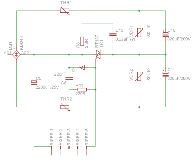
The first suggestion was to see if there were any significant dips in the voltage across the input smoothing capacitors. But the voltage was rock solid around the 330V mark on the DM DC range of my Digital Multi-Meter.

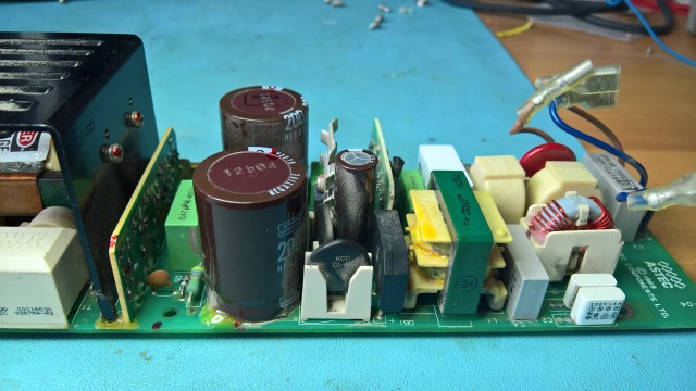
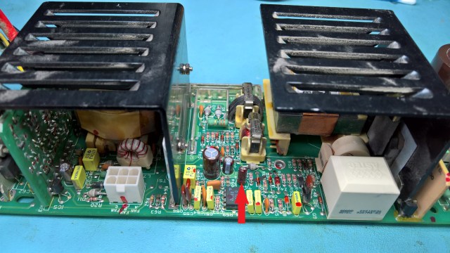
The second suggestion was that perhaps something was shorted on the outputs, causing the overcurrent sensing to switch it off. Some suggestions talked of checking low value resistors for shorts, there are two 10ohm resistors, and one looks like it has a bit of physical damage, but they both measured fine. I also checked the capacitors across the 5V output, particularly the ones that I had not by then replaced, they seemed OK. Nevertheless I decided to replace the two big ones across the 5V output just in case, particularly the 3300uF one (can’t see a label to reference it) which measured a bit high on ESR, the 8200uF one also had a relatively high ESR, so it was worth replacing too. Replacing them failed to make a difference.

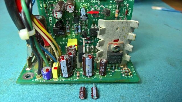
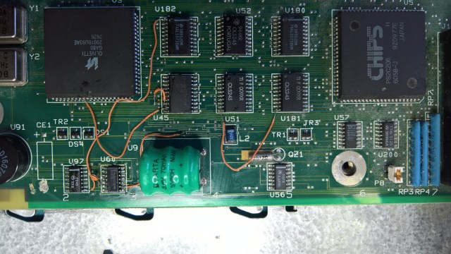
I then had a closer look at the riser board on the output section, as this is probably doing the regulation. I noticed that C407 (120uF 25V) was measuring high on ESR, and then I realised there were signs of leakage. There were also some marks (heat perhaps?) around C408 (120uF 16V). I decided they should be replaced.

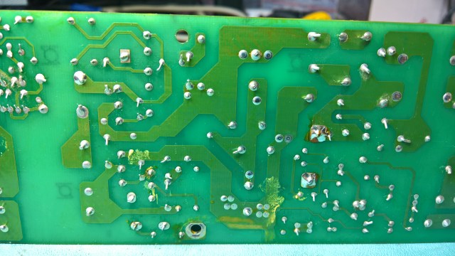
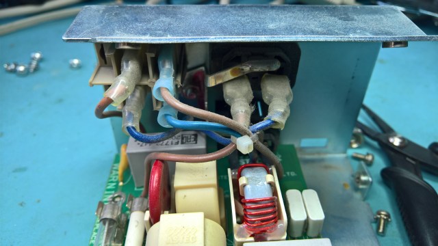
Having removed C407 I realised it had definitely leaked. Reaching C408 was going to be hard, so I removed the whole riser. This would make it much easier to repair and clean, and I could see that there appeared to be some cleaning needed. Once I got the riser out I could see some shiny residues on the underside, I am not sure that they can be capacitor leaks, but they did look a bit like it.

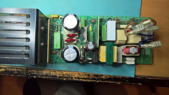
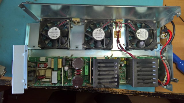
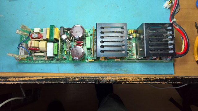
I finished replacing C407 and C408 and cleaned everything up. This is the result:

I re-installed the riser and tested it again. I used the MicroVAX 2000 load board on the 5V output. This time all the fans turned immediately, the 5V output looked good, and there was no significant ripple. The 12.1V output measured 12.4V though, I am not sure if that is OK or not.

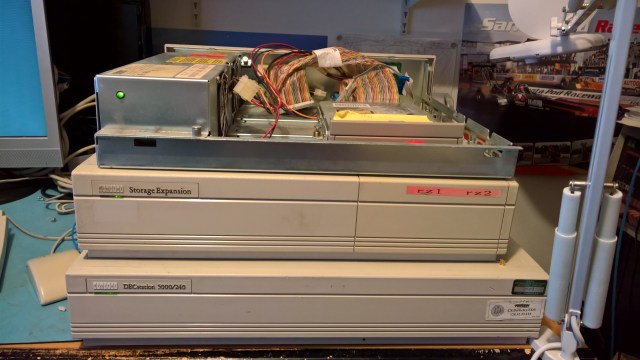
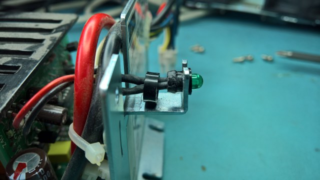
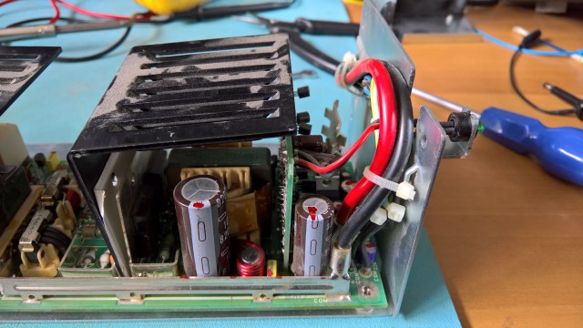
I partially reassembled the PSU and installed it in the machine. The machine ran fine, I ran the self tests a few times and left the machine running for around an hour or more and it stayed running. So I finished reassembling the PSU, re-soldering back the LED wires and finally reassembled it again.

I replaced quite a few capacitors in the end:

H7878 Parts Replaced

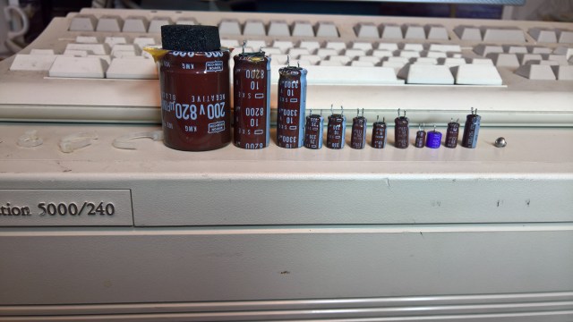
Here it is, working once more:

Posted in DECstation 5000/240, Retro-Computing | Tagged | 4 Comments

DECstation 5000 Model 240 PSU Failing Under Moderate Load

The H7878 PSU in my recently acquired DECstation 5000 Model 240 had a shaky start and then stopped working altogether. I found a problem with the input rectifier smoothing capacitors, at least one of them anyway. It was a real job to remove them because they had been epoxied on. I had to cut the first one, somehow I was able to remove the second intact. The one I cut did not have any liquid electrolyte, although the core was damp with it, I am not sure if that is normal or not.

Notice the cardboard disc that was underneath the capacitors. It seemed clean in both cases, so I am not sure if there was leakage or not. The card discs seem to be there to isolate the base of the capacitors from some contacts on the board, so I kept them. The replacement capacitors were slightly smaller so you can see the cardboard discs now.

PSU With New Smoothing Capacitors From Above

After I put it back together I first tried turning it on with no load. The fans twitched once. I assumed that as there was no load the PSU was shutting down immediately. So I put it back in the machine, but nothing happened when I powered it on, the fans did not move at all. I later realised this was probably because the PSU cannot handle the load.

I took the whole thing out again and checked it over. The rectifier voltage across the newly replaced capacitors was looking good. I then measured the outputs of the main transformer. The three outputs seemed to be producing 50VAC, 1VAC and 8VAC. So the inverter and the main transformer seemed to be working fine.

I then realised that the PSU was actually producing voltages on its outputs. I put a 10W 15ohm resistor across the main 5V output and got a voltage of about 5-6V. The ripple looked like it might be high though. So I replaced as many of the output stage capacitors as I could easily reach. These were:

Label Value Voltage
C21 220uF 25V
C36 2.2uF 50V
C26 (see below) 10uF 25V
C24 330uF 16V
C40 120uF 25V
C41 120uF 25V

C26 was a bit different. It was a small purple capacitor made Sanyo, it was marked simply “10 25”. Since it is on the 12V output I guessed this meant that the “25” referred to the voltage. Below are some pictures of this capacitor:

After replacing all these I found that the behaviour was not a lot different, although ripple seemed to be much improved on the +5V output. The 12V fans twitch for a bit and then one of them will start running. The +12V output starts at around 1.5V and then after about 5 seconds or so it rises to +6V, whereupon one of the fans will start running, the +12V output then varies between +5V and +7V, sometimes dropping as low as 4V or rising as high as +8V. This happens when I load the +5V output with a 10W 15ohm resistor, no load for the -12V output, and the fans loading the +12V output.

If I put a bit more load on the other outputs then the +12Voutput won’t rise above 1V or so and the fans don’t even twitch. I tried a 2ohm load on the +5V output and that kills the +12V output, even though the +5V output is rated at 40A. Similarly I tried a 66ohm load on the -12V output and that too kills the +12V output. The -12V output is rated at 0.2A, so I am close to the rated limit in that case.

Basically it seems that the PSU simply cannot cope with much load.

Posted in DECstation 5000/240, Retro-Computing | 1 Comment

DECstation 5000 Model 240 H7878 Possible Fault Found

As previously reported, the H7878 PSU in my DECstation 5000 Model 240 has failed. Today I examined it more closely and I think that I know what at least one of the causes of the problem is.

I started by looking to see if I could see any obviously damaged parts, and I tested the transistors with a diode tester. Nothing obvious except one resistor which appears possibly to have a little damage, but its resistance appears correct.

I checked the grounding and I saw that the whole PSU, primary and secondary side is mains earth referenced when installed in the enclosure. So I must be careful to only connect the scope probe ground lead to mains earth reference, which can be the enclosure itself.

Further checking showed that there is some mottling on the underside of the board, seemingly where the two big smoothing capacitors are, one of them does feel as if it is slightly bulging at the top, but ESR seemed fine. I also noticed C15, a Rifa 3300 pF Y class paper capacitor, that looks a little cracked, but probably still OK for the time being.

H7878 Underside of PSU Board Showing Possible Leakages

Underside of H7878 showing possible leakage near one of the smoothing capacitors.

I started testing the PSU with power. I found that input is coming in to the board OK. Next I tested the output of the big filter capacitors. This seemed to be around the 170V on the DMM DC range, and a steady 136V on the DMM AC range. This does not seem high enough. My understanding is that the rectified DC that comes out of an input rectifier such as this one should be around 325V. The rough and very incomplete schematic for this stage is:

H7878 Input Rectifier Schematic

H7878 Partial Schematic for Input Rectifier

I checked the resistance of the two capacitors (C10 and C11) with a digital multimeter. One slowly charges, the other appears open circuit immediately. It seems to me that one of them is faulty and the voltage should probably be reaching 325VDC on the rectifier output, not 170.

H7878 Input Rectifier Smoothing Capacitors

H7878 Input Rectifier Smoothing Capacitors. Note the Epoxy holding them in place.

Removing these is going to be very difficult because of the glue holding them down. I am wondering if I should just cut them.

Posted in DECstation 5000/240, Retro-Computing | Leave a comment

DECstation 5000 Model 240 H7878 Power Supply Failure

When I first got the DECstation 5000 Model 240 I noticed that it would power off after a period of operation. This suggested a problem with the H7878 power supply. I had already inspected it for any obviously leaky capacitors and they all looked OK, but a friend has told me that some of the capacitors in this power supply are suspect. So, before really getting into making this machine work again, I took the PSU out and decided to take a closer look at the capacitors.

H7878 PSU Opened For Inspection

H7878 PSU Opened For Inspection

So that I would be able to reassemble it, I took a picture of the power entry connections:

H7878 PSU Power Entry Connections

H7878 PSU Power Entry Connections

However, the problem was at the other end where the power LED is installed. I could not remove the power LED without causing damage:

H7878 PSU Power LED

H7878 PSU Power LED

So I did another visual inspection of the capacitors and put everything back together again. I powered on the machine very briefly and it started booting. Then I decided it would be better to put the cover on so there was better airflow, particularly if the PSU was shutting down because of any kind of overheating. After I put the cover back on the PSU would not work at all, no fan movement, no LED. So now the PSU has failed completely.

I took it apart again. This time to get the LED out I de-soldered the wires going into the board. To do so I had to partially remove a heatsink, even that though would not come out, despite unbolting the transistor heatsinks.

H7878 Removing The LED

H7878 PSU. Removing the Power LED

After removing the wires from the LED I was finally able to get the board out to inspect it:

H7878 PSU Board Removed

H7878 PSU Board Finally Removed

I found two small capacitors that had a high ESR so I replaced them. The first was the one marked below:

H7878 PSU Board With High ESR Capacitor

H7878 PSU Board With High ESR Capacitor Marked

The second was in the position marked in the photo below, although I took the picture after replacing it. That one was very fiddly to replace because I could not easily access the back of the riser card without removing much more stuff, so I did it in-place.

H7878 PSU Board With Removed High ESR Capacitors

Sadly, despite replacing the two capacitors above, the PSU still does not work. So more investigation is now required. Probably a transistor has failed.

Posted in DECstation 5000/240, Retro-Computing | Tagged | 1 Comment

DECstation 220 Monitor Sense Circuit Problem

Updated 2017-08-27. I was using a datasheet for the LM339 that was incorrect, the paragraph where I talk about the expected results has been changed accordingly.

In my last post about the work to get my DECstation 220 working again I reported that I had found a possible problem in the monitor sense circuit. I have replaced the comparator, and the buffer (74LS244) that the comparator drives, with no change in the signal. I also found a capacitor with high ESR in the area, so I replaced that. However, the monitor sense signal is still stubbornly fixed high and not changing as it does on the better-working original board.

I have reverse-engineered the circuit and, as best as I can tell, it looks like this:

DECstation 220 Monitor Sense Circuit

The monitor sense signal goes to the Paradise PVGA1A chip from the Y4 (pin 3) output of the 74LS244 buffer.

I have measured the reference voltage on pins 5, 7 and 9 of the comparator to be 0.36V. The Inmos G176 is putting out a waveform on pin 3 which oscillates from 0v to 1V at a frequency of approximately  600KHz, with peaks 300ns long, while pins 1 and 2 of the G176 are always at 0V.

This should result in pins 2 and 14 of the comparator always being off, while pin 1 would pull the output down to 0V during the peaks on the pin 3 signal from the G176. Which would result in pin 17 on the 74LS244 buffer always being at +5V except during the peaks coming from pin 3 of G176, when it should drop to 0V.

As I said above, I have replaced the LM339, the 74LS244, and also C105. I have checked for any more components in the circuit and I have not been able to find any. I have measured the pull up resistor in-circuit and its resistance looks to be as per the marking. I cannot work out how it is possible for the comparator output never to go low, unless the peaks from the G176 are too short.

Addendum 2017-08-27. For comparison, on the original board, where I get a corrupted video display, the G176 outputs rather different signals, with a signal on pins 1, 2 and 3, the signals seem to vary in amplitude from 1V to 2V. I can’t see the length of the peaks though because the signal is too irregular, unlike on the board in question. The difference in behaviour could be either cause or effect, because, I assume, the BIOS is telling the G176 what to do and that may depend on whether it has sensed anything at all. Or it could just be a faulty G176.

Posted in Retro-Computing | 1 Comment

DECstation 220 Faulty Parts Found

I have been doing more work on the DECstation 220. As I commented in my previous post, it is only putting out a corrupted pattern to the screen because it is not writing anything to the video memory, apparently because the EMEM signal to the PVGA1A chip is incorrect.

I have found what I think is the reason for the EMEM signal looking wrong. At first I found that a couple of pins on one of the custom gate arrays seemed shorted together. This would have been a disaster as those gate arrays cannot be replaced with standard parts. But then I discovered that they were connected to the Chips and Technologies 82C206, and I realised that a lot of the pins on the 82C206 appear to be shorted together. I suspect that the chip may have got damaged as a result of powering it on when other parts were damaged by the battery leak. This chip can at least be replaced.

However, as it is a surface-mounted PLCC84, it will take some doing to replace it. I have a spare board where the 82C206 seems to be OK, but it does not beep or produce a video output of any kind. I would like to use the partially working original to get the spare working better, and it is best to do that before removing the 82C206. This is because I could damage something else in removing the 82C206, and as the original board gets further into the boot sequence than the spare does, it will help to have something to compare against while trying to fix the spare.

So I have switched my attention to the spare for now. I have been trying to find out why it won’t produce any video output at all. I have found that there is an Inmos G176 which outputs the colour palette and that this output is also sent to a set of 3 comparators (on an LM339), these comparators drive the monitor sense signal that goes to the PVGA1A. However I have found that the comparators are not producing valid output, the input signals are varying above and below the reference voltage, but the outputs never change. So I will have to change the LM339. I don’t have any so I am going to have to order some.

I am not totally convinced this will fix the spare board, it may yet be failing earlier in the boot sequence, we shall see when I replace the LM339.

Posted in Retro-Computing | Tagged | Leave a comment

DECstation 220 Update

Previously I reported that I am now getting corrupted video out of the DECstation 220. I have spent the last couple of weeks trying to understand the problem, checking the tracks to all the chips in the battery-damaged area, on both the original and the spare motherboards. I have also double-checked the tracks and vias in the damaged area to see if I missed any bad tracks. I have not found any new problems. In doing so, I have partially reverse engineered the schematic using Eagle. The partial Eagle schematic is here.

BA241 Partial Schematic

A partial Eagle schematic of the BA241 CPU Board from the DECstation 220

I decided to put the board back in the machine, after re-fixing one of the repair wires that had come loose. You can see my repairs in the photo below. As you can see, I am not very good at it, the repairs seem to work, but they are not neat and have poor mechanical strength. If anyone would like to offer any tips on how to do it better I would love to hear them.

DECstation 220 Track Repairs

My poor quality track repairs on the DECstation 220 motherboard.

I still get the corrupted video, but this time I get some clear beep codes, 1 long, 3 short, 1 long. However, every manufacturer used different beep codes, and I have not been able to find the specifics for this board. However, in searching for the beep codes I discovered that this machine is actually a re-badged Olivetti M250-E, and I found a pocket service guide here. This at least told me what the jumpers are.

I tried to do a bit more analysis of why the Paradise PVGA1A chip does not seem to write to the video memory. One possible thing that came to light is the EMEM input (pin 21), I found that this is high, but the trace on my scope for this signal is strangely faint, which makes me think there is something odd about it. This signal comes from a buffer whose input is tied to zero, the enable input of the buffer is also faint on my scope, but generally low. I have a feeling that the buffer enable is supposed to be low most of the time so that another source of EMEM can be used, but I can’t find that source and it looks like the signal could be floating as a result, which may explain why the signal is faint on the scope, but I am not at all sure.

I also found that MWRN (Pin 32) on the PVGA1A was never active. I could not trace its source either. I am not sure if this could be another reason why the PVGA1A never writes to the video memory.

One jumper is interesting as it disables the onboard VGA. Which made me think that if I installed an ISA VGA card on the riser, I might be able to get some video out of it. I am pretty sure I have an ISA VGA card, but I have not been able to find any yet. When I do I will give it a go, but for now I am going to have to put the machine away, as I don’t know how to diagnose the VGA problem any further.

Posted in Retro-Computing | Tagged | Leave a comment