Updated 2017-08-27. I was using a datasheet for the LM339 that was incorrect, the paragraph where I talk about the expected results has been changed accordingly.
In my last post about the work to get my DECstation 220 working again I reported that I had found a possible problem in the monitor sense circuit. I have replaced the comparator, and the buffer (74LS244) that the comparator drives, with no change in the signal. I also found a capacitor with high ESR in the area, so I replaced that. However, the monitor sense signal is still stubbornly fixed high and not changing as it does on the better-working original board.
I have reverse-engineered the circuit and, as best as I can tell, it looks like this:
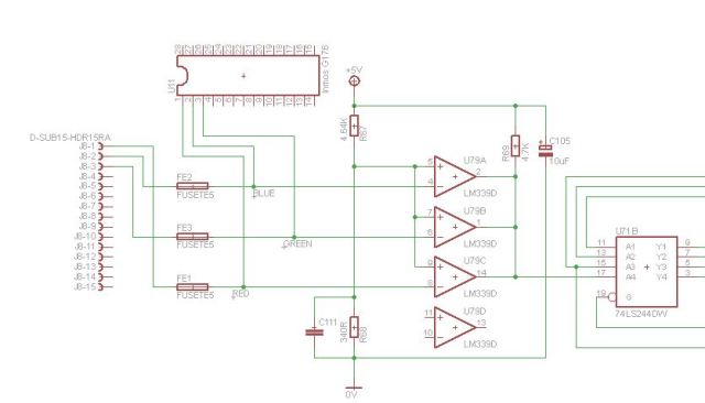
The monitor sense signal goes to the Paradise PVGA1A chip from the Y4 (pin 3) output of the 74LS244 buffer.
I have measured the reference voltage on pins 5, 7 and 9 of the comparator to be 0.36V. The Inmos G176 is putting out a waveform on pin 3 which oscillates from 0v to 1V at a frequency of approximately 600KHz, with peaks 300ns long, while pins 1 and 2 of the G176 are always at 0V.
This should result in pins 2 and 14 of the comparator always being off, while pin 1 would pull the output down to 0V during the peaks on the pin 3 signal from the G176. Which would result in pin 17 on the 74LS244 buffer always being at +5V except during the peaks coming from pin 3 of G176, when it should drop to 0V.
As I said above, I have replaced the LM339, the 74LS244, and also C105. I have checked for any more components in the circuit and I have not been able to find any. I have measured the pull up resistor in-circuit and its resistance looks to be as per the marking. I cannot work out how it is possible for the comparator output never to go low, unless the peaks from the G176 are too short.
Addendum 2017-08-27. For comparison, on the original board, where I get a corrupted video display, the G176 outputs rather different signals, with a signal on pins 1, 2 and 3, the signals seem to vary in amplitude from 1V to 2V. I can’t see the length of the peaks though because the signal is too irregular, unlike on the board in question. The difference in behaviour could be either cause or effect, because, I assume, the BIOS is telling the G176 what to do and that may depend on whether it has sensed anything at all. Or it could just be a faulty G176.

Pingback: More Leaking Batteries | Rob's Old Computers