[Updated 14th October 2023]

I acquired a VT100 a while back. It was just the video unit, without a keyboard, but I have a couple of keyboards for my VT101 and VT102, so I would be able to use it once I had it working.
My first job was to inspect it, particularly the power supply and the video monitor boards. It looked like some parts had been replaced on the PSU and there was a track that had been cut. The result does not match the schematic, but a friend has a similar situation with his VT100, so I was not too concerned. I also found that the heatsink for one of the 7812 regulators (Z2) was not properly attached with a screw, so I added a screw.
I then decided to reform the two big capacitors in the PSU. My bench equipment only allows me to go up to 60V though, which they did without issue. Given that they were OK up to that point I decided to test the PSU as a whole on the bench with an artificial load, just to be sure the whole thing was working OK. The picture below shows the connector marked up for which output is which.
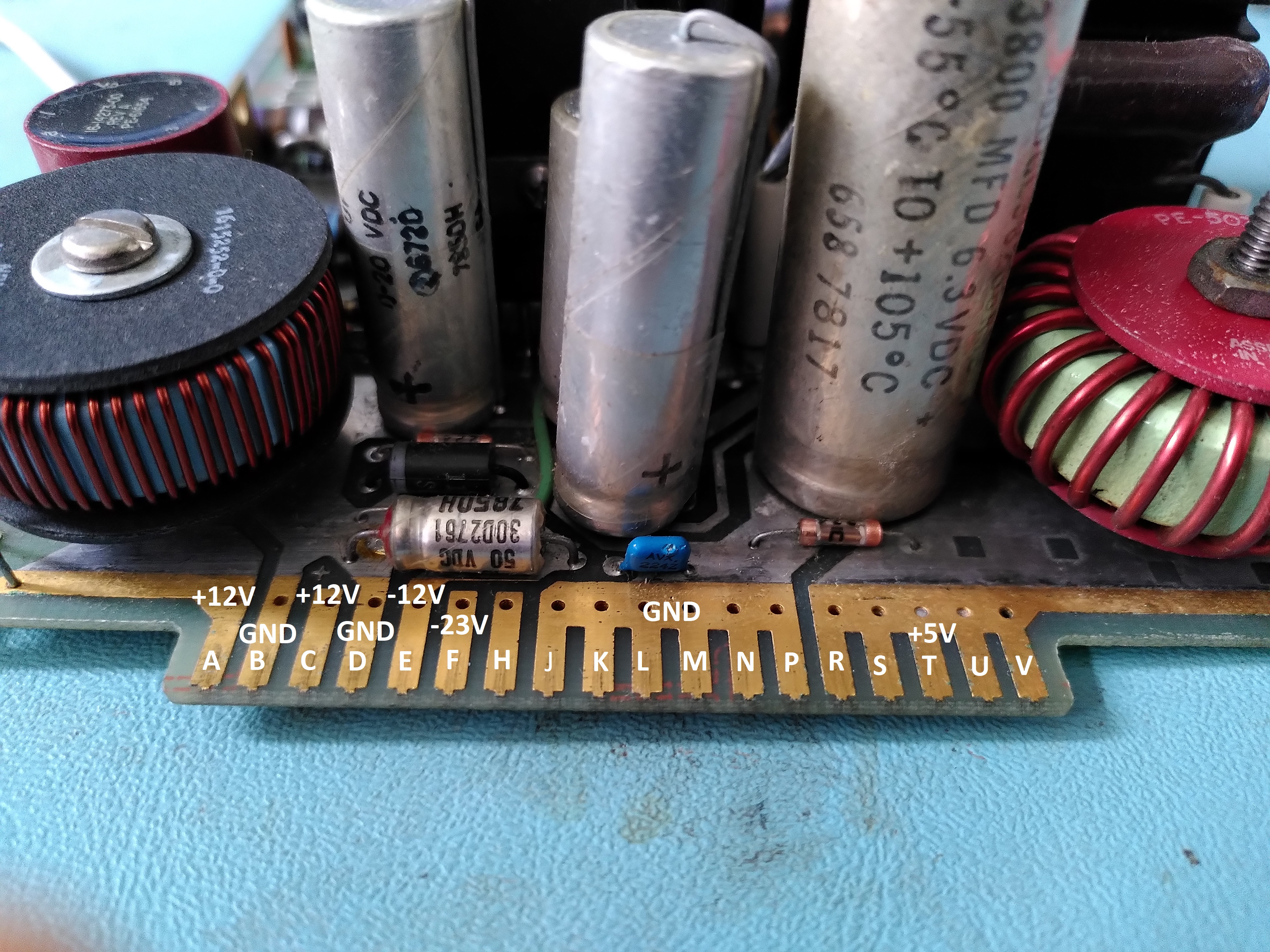
The PSU tested OK for voltage and ripple. Except the -23V output which went to -31V. However, I am told that this output is pulled to -23V by two Zener diodes D2 and D3, as shown on the schematic on page 14 (B4-C4) of MP00633_VT100_Schematic_Feb82.
The apparently unused pin H of the PSU board connector turns out to lead to a cut on the track and patch wires, so there is clearly an ECO that is not shown on the schematic.
I also decided to replace the electrolytic capacitors on the video monitor board, in the interest of avoiding damage to parts that are difficult to replace (especially the flyback transformer, although I don’t know if the capacitors could cause it damage if they were bad), and also in the interest of getting a clean stable image. I did not replace the non-polar capacitor mainly because they are hard to find. I also took note of this and changed C439 from a 7uF 6V part to a 100uF 100V part.
At this point I was ready to try turning it on. Of course it was a major disappointment that there was no life from it, but I guess not totally unexpected. Nothing on the screen, no beep, no LEDs lit up on the keyboard, nothing.
I went through a number of troubleshooting steps to trace the issue, following some troubleshooting steps in the Technical Manual. I could see that the DC012 video processor control chip was permanently asserting the interrupt line and not generating any DMA HOLD REQUESTs. I wondered if this might be because the firmware hadn’t got to the point of initialising it, perhaps because of bad ROMs. I dumped them with help from my friend at 9track.net (a device to allow different Chip Selects to be used) and they looked fine, matching the ones posted here. Only one of the ROMs is posted on 9track, I dumped the other three. The all the dumps plus the disassembly of the first one are here.
After disassembling the first ROM I used a logic analyser to see if the 8080 was executing instructions correctly. I was able to see that it was following the instructions in the ROM, so the 8080 CPU is fine. I could see that it was supposed to send the self-test status to the keyboard LEDs, but for some reason these would not light up on the keyboard. One of my keyboards has a suspect cable. I wasn’t sure if it was down to that, so I put the logic analyser on the UART to see if I could see what it was sending to the keyboard. I was able to see it sending the codes to light all the LEDs, then sending codes indicating the ROM tests and finally the RAM test. It never sent another code after the RAM test, so I concluded that the RAM test was failing.
Looking at the disassembled code I found the RAM test code and could see that it writes 0x00 and then 0xAA to every location, I think it also tests 0x55. After a few false starts in trying to observe the RAM test with my logic analyser I was finally able to see the reads properly by triggering on the rising edge of the MEM RD pin on the J1 connector. This showed me that the reads stopped at a particular address, indicating that the 2114 chip labelled E51 in the schematic was returning a A when it should be returning a 0.
Initially I misidentified this because I thought it was a misread of the 0xAA, however it turned out that it was a misread after checking that the initial 0x00 could be read back, it was reading back 0x0A. It is a bit suspicious that it was always returning 0xA in the lower nibble.
Once I replaced the suspect chip the RAM test started to pass. I could also see from my logic analyser that the interrupt routine which clears the vertical frequency interrupt is invoked at 60Hz. So the RAM test is now passing.
Plugging in the keyboard, I now get a beep and the ON LINE LED lights up. However a few moments later all the keyboard LEDs come on and keyboard beeps continuously. The screen also remains resolutely blank.

Pingback: VT100 Keyboard Constant Clicking Fault | Rob's Old Computers
Hey, have you managed to bring that terminal to life? I’m currently troubleshooting a VT-100 too.
Almost, I can get it to work on the external output. I think it needs a new flyback transformer, and one component gets very hot and I am worried there is something else wrong, perhaps too many spikes on the power rail.