I have been repairing a VT100 that I acquired a while ago. I have got it to the point where it works except for the actual video display, as described in a previous post. I wanted to try to get it to show an image on the CRT.
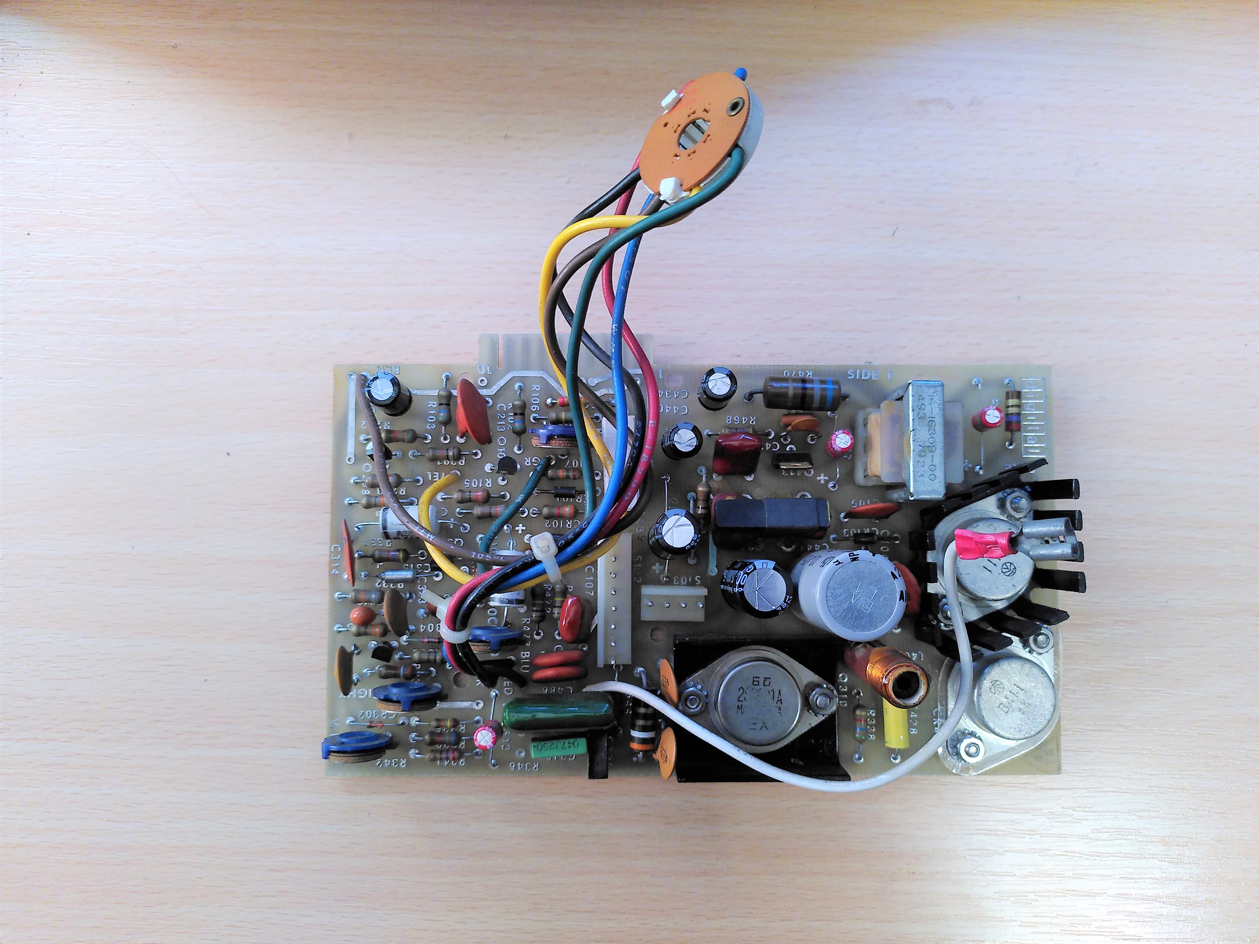
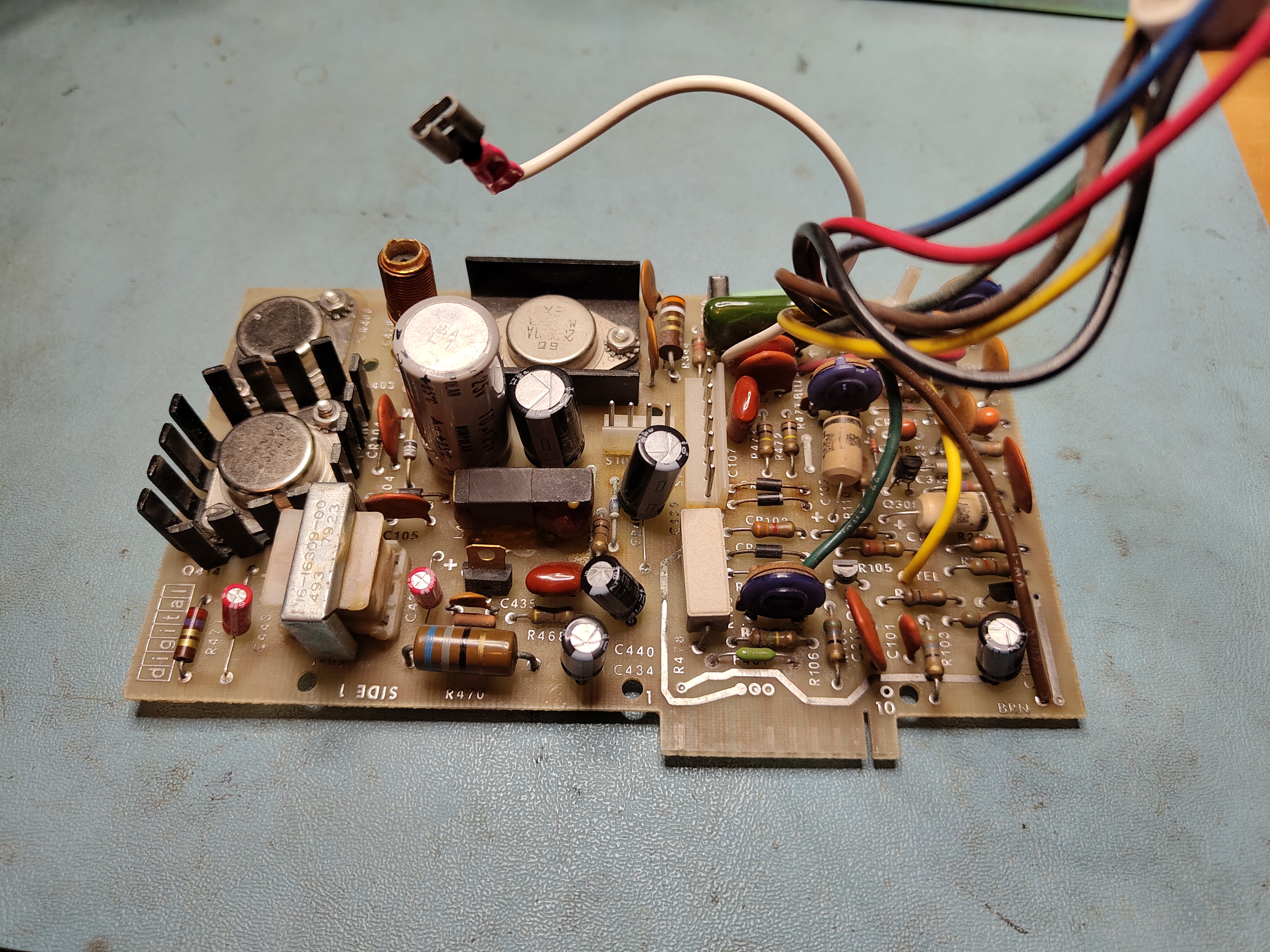
The first problem is that my Elston monitor board does not match the schematic in the February 1982 print set. My VT100 seems to be an older version described in the March 1980 print set but this print set does not include the schematic for the monitor board. My board has two transistors in a TO3 package for Q414 and CR406. The February 1982 print set has quite a different layout. This is my monitor board after I had replaced some of the electrolytic capacitors:
Monitor Board After Recapping
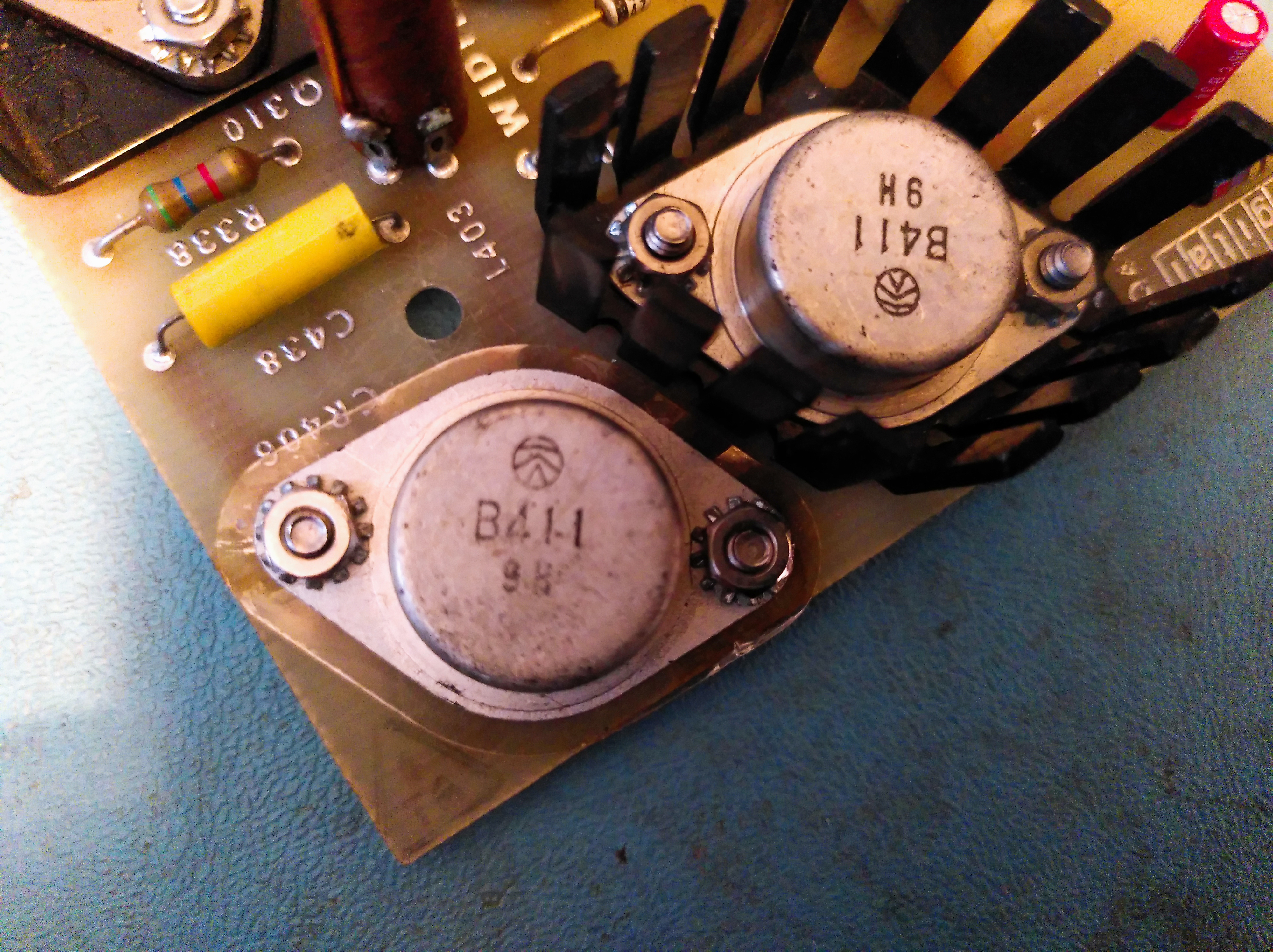
It turns out that Q414 and CR406 are actually 2SB411 germanium transistors. A version of the schematic exists for the Micro-Term MIME-1 terminal on p53 of the PDF of the technical manual.
The first problem I found was that the monitor board did not seem to be receiving any power. This turned out to be the fuse, F401, that has blown. I guess the fact that this had blown was a bit suspicious, there was no obvious reason why it might have failed, but the worry here is always the flyback transformer.
Initially, on advice, I replaced the fuse with a 12V car bulb to act as a current limiter. This showed there was no dead short on the output side of the fuse. After replacing the fuse I switched on the terminal. There was no glow from the filament and I thought I could smell burning, so I switched it off immediately. The fuse remained intact though.
On further advice I tried removing various parts. It was at this point that confusion reigned about Q414 and CR406 because they did not measure like the transistors in the February 1982 schematic. It took some time to realise they really are germanium parts and that my board is an older version.
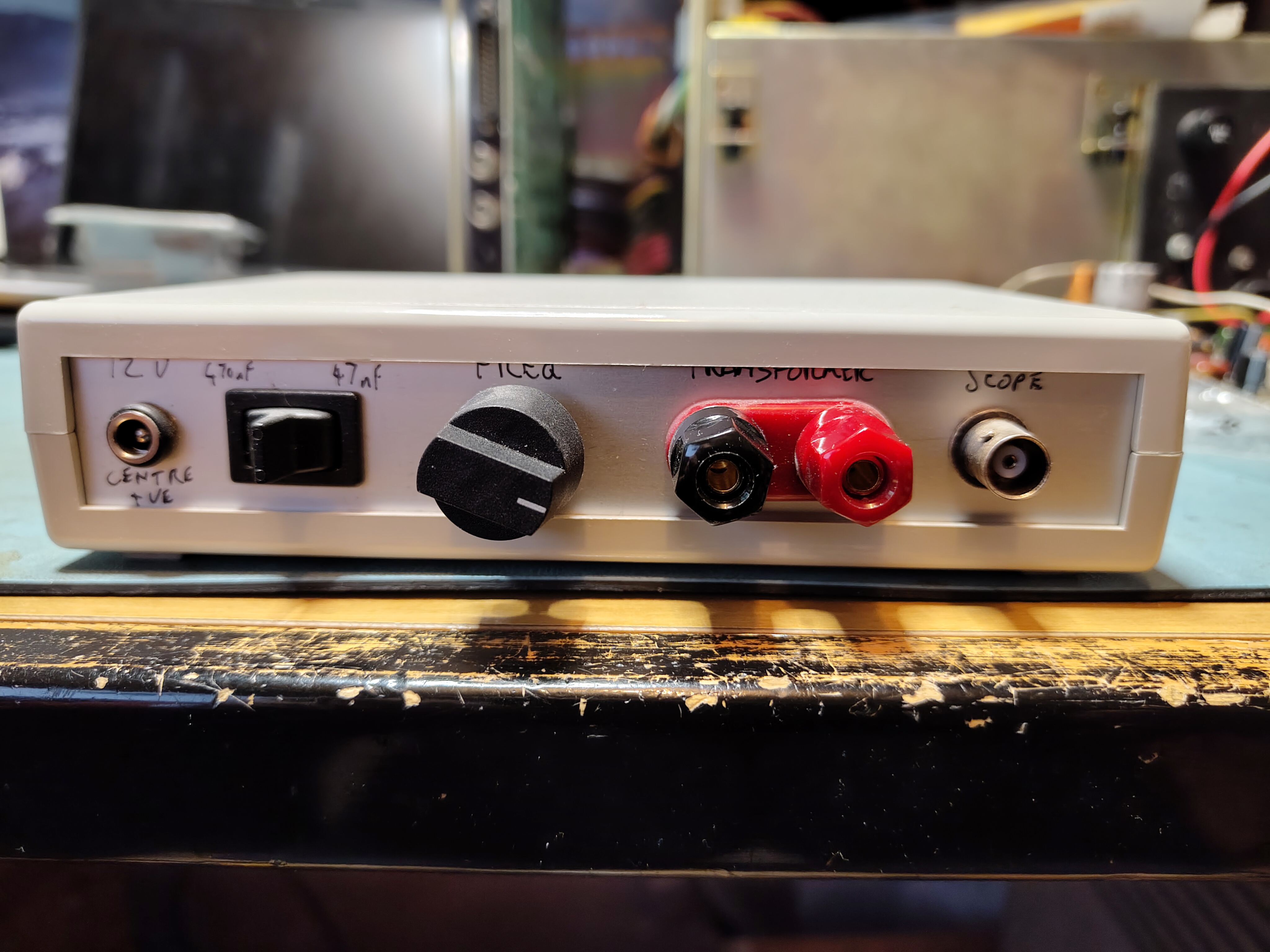
To test the flyback transformer for shorted coils I needed to conduct a ringing test. I was sent the details of a circuit that can be used to do this. The circuit was described in an article published in the September 1993 issue of Television magazine. I built the circuit and put it in an enclosure. This is my ringing tester:
I tested each winding following the schematic to identify them. These are the results:
VT100 Brown-Red Ring TestVT100 Black-Violet Ring TestVT100 Black-Green Ring TestVT100 Yellow-Brown Ring TestVT100 Yellow-Red Ring Test
The Brown-Red and Black-Violet coils only have a few turns so all these results appeared reasonable.
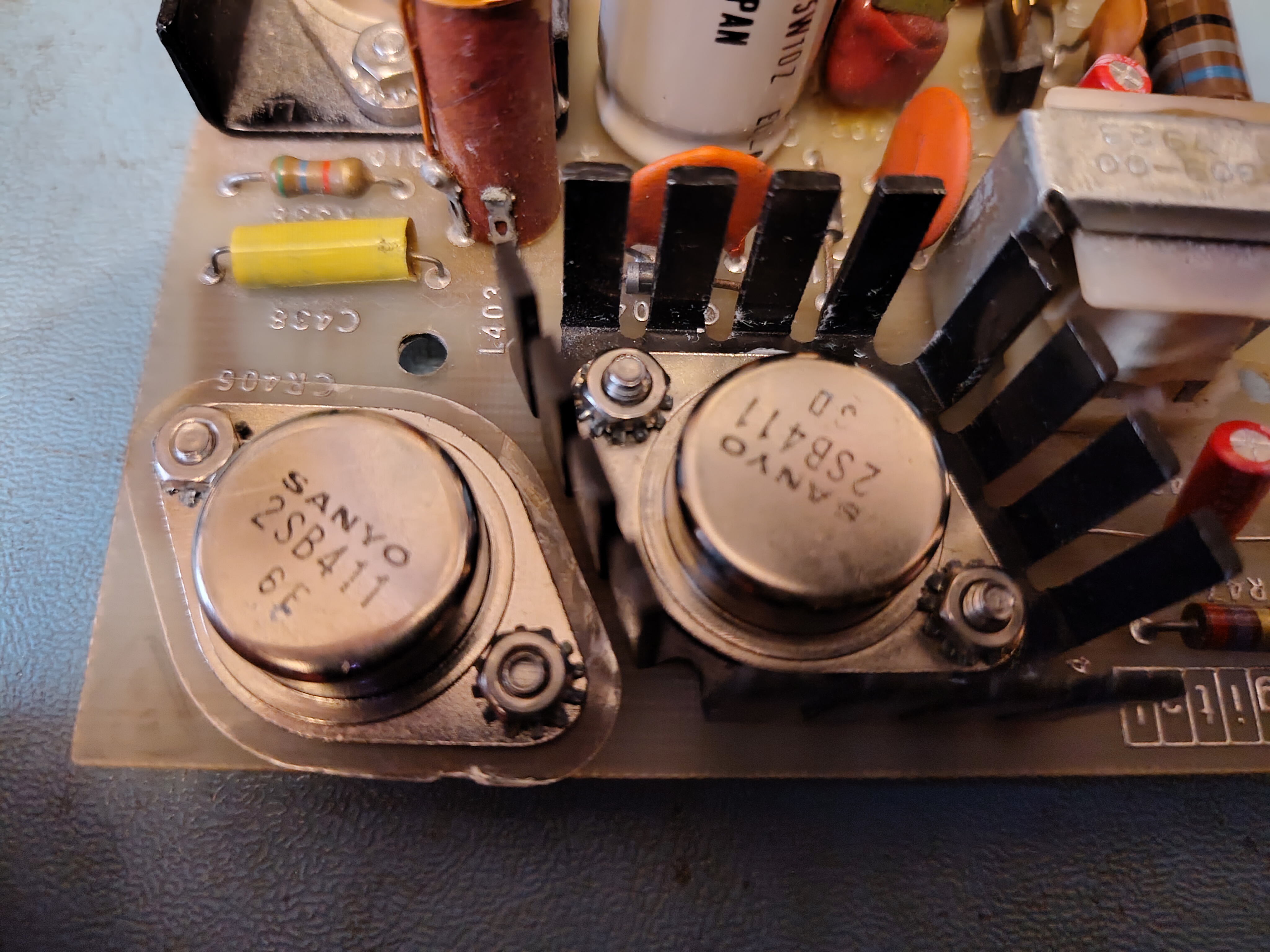
As mentioned above, the germanium transistors, Q414 and CR406, were not measuring well. I have a Peak Atlas DCA 55 component tester, it identified them as three terminal bicolour LEDs. I sourced some new old stock replacements. These were identified correctly as germanium PNP transistors so I fitted them, applying some fresh TIM to the one with the heatsink, and decided to risk trying again. I also had to repair the wires going to the neck of the tube, metal fatigue had broken some of them where they were attached to the board, this may have been why the filament had not glowed in earlier tests.
Original Germanium 2SB411 TransistorsNew Germanium 2SB411 Transistors
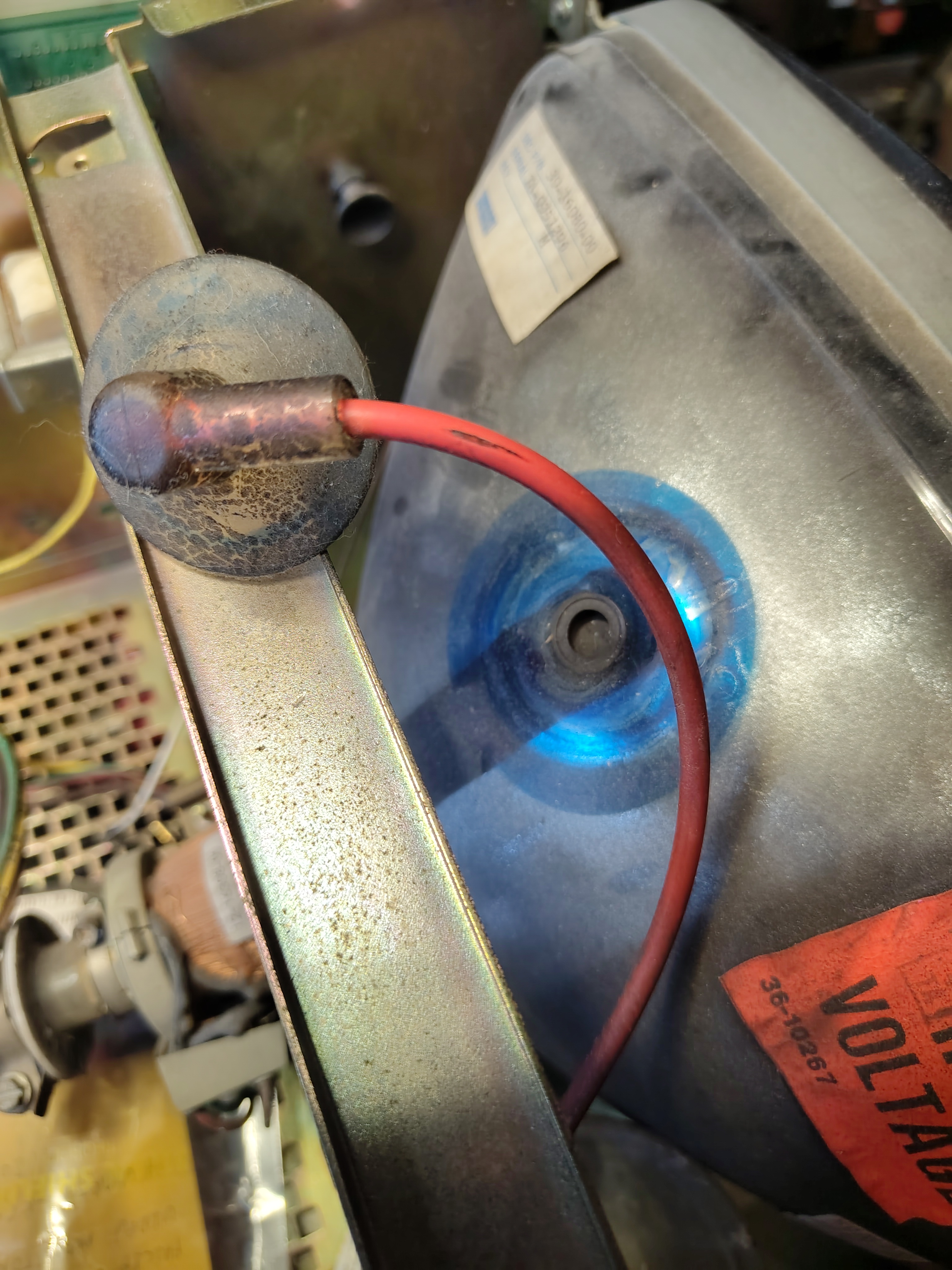
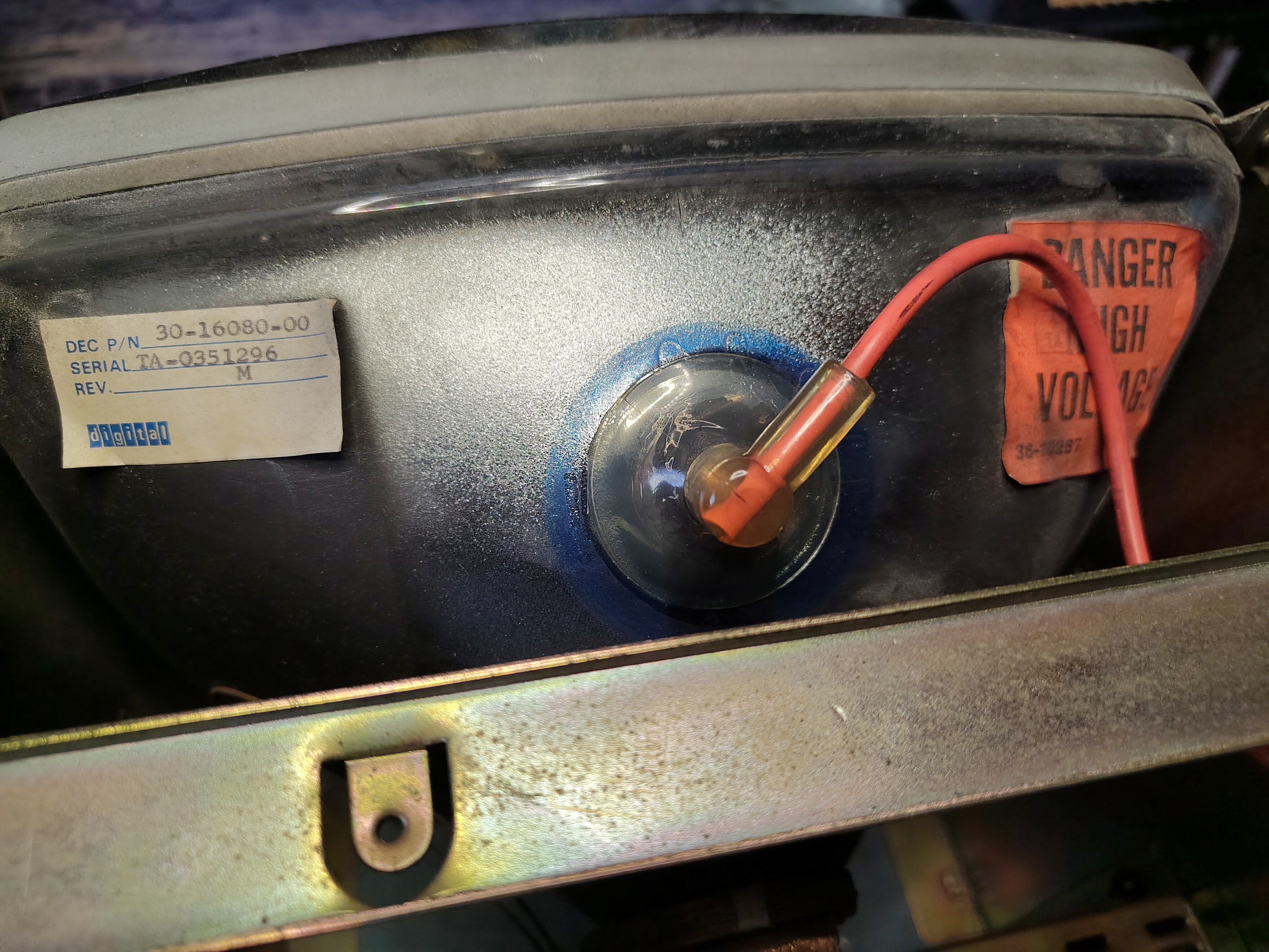
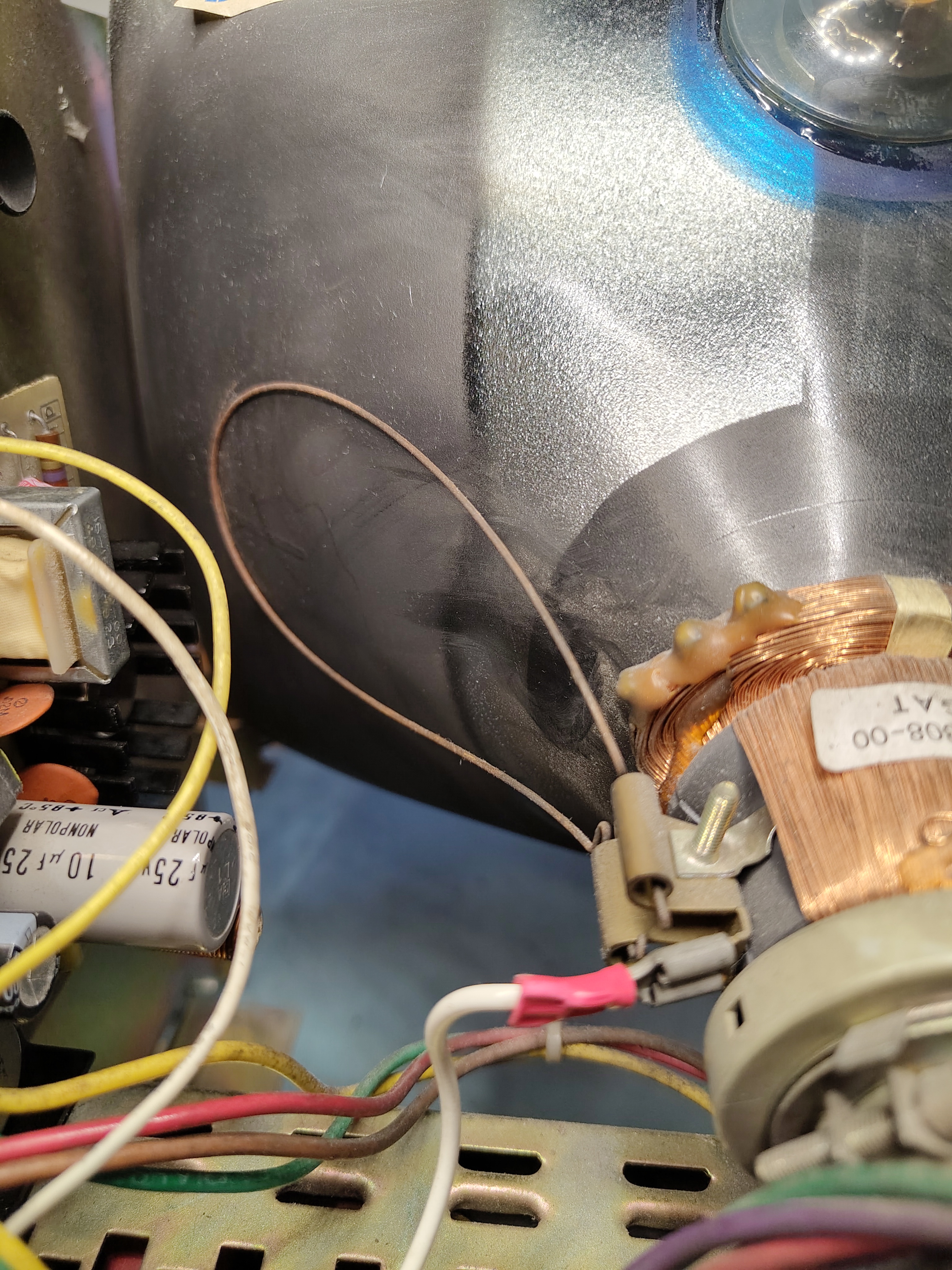
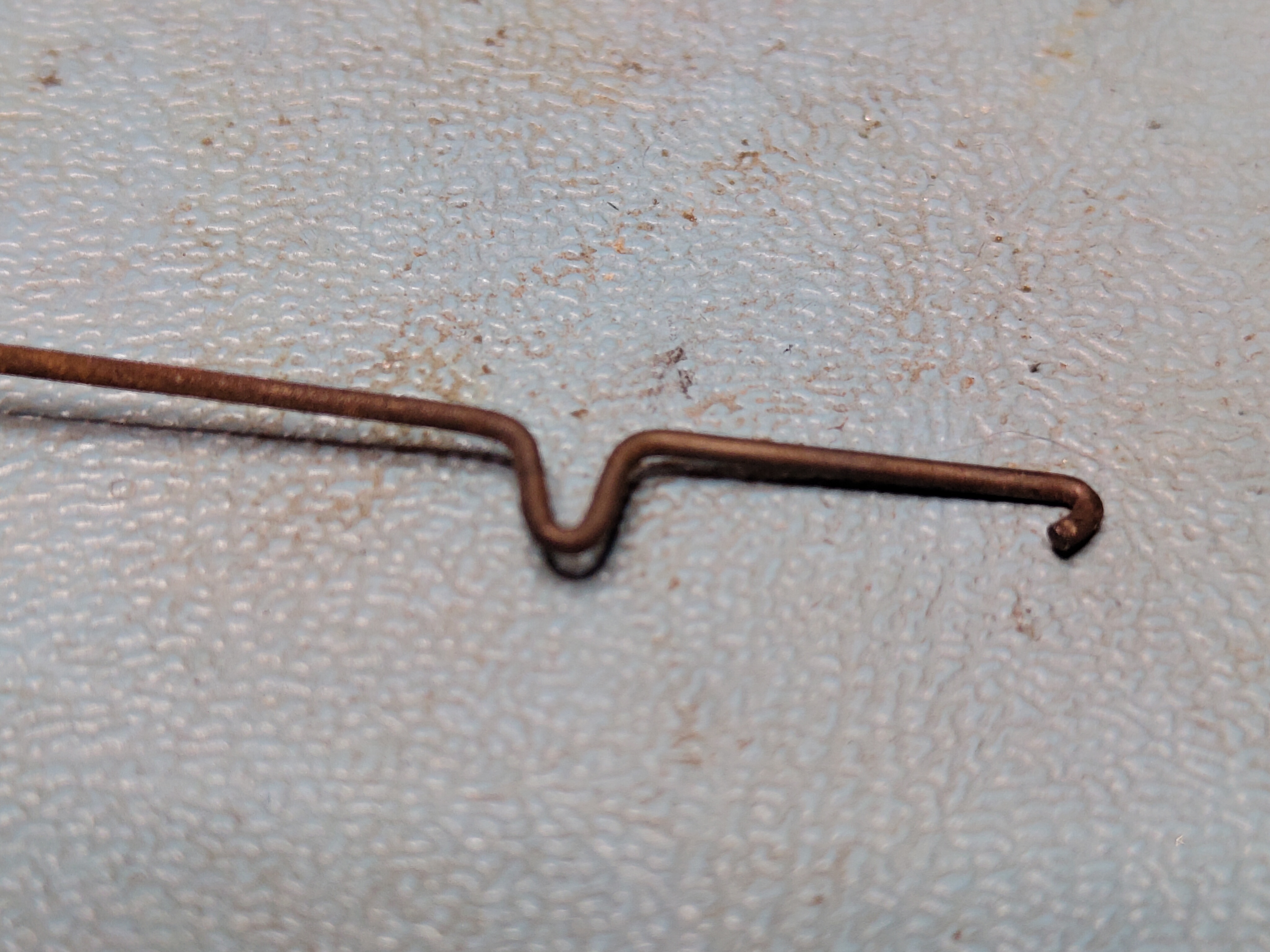
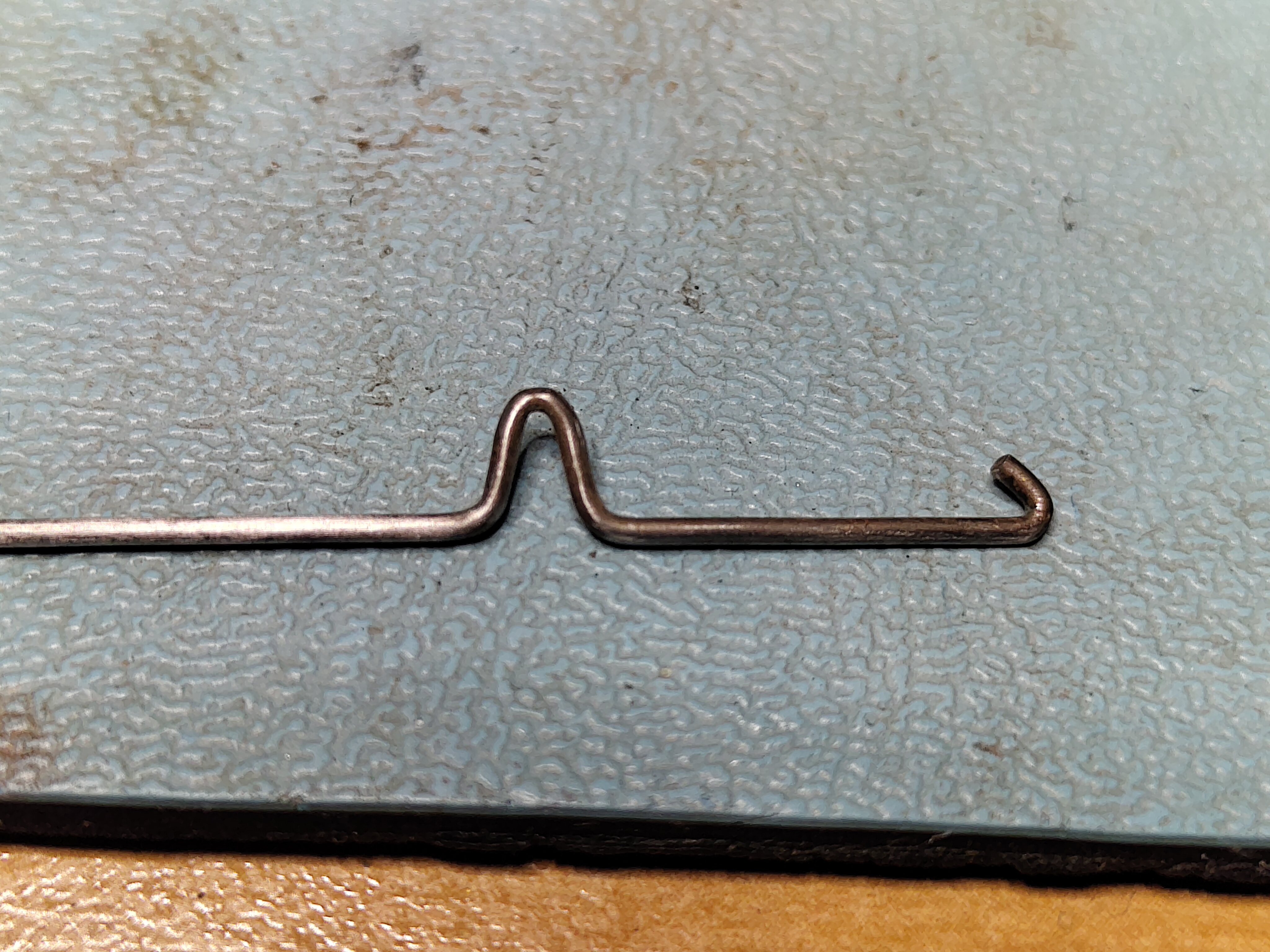
I cleaned up the anode cap and the area around the anode cap on the tube itself, finally and applying fresh silicone grease. Then I noticed that the grounding wire that contacts the aquadag on the outside of the tube was corroded and not making electrical contact, so I cleaned that up too and checked it was making good contact.
VT100 Anode Cap Before CleaningVT100 Anode Cap After Cleaning and Fresh Silicone GreaseCorroded Ground SpringCorroded Ground SpringCorroded Ground Spring After Cleaning
I switched on the terminal but got the same result, a faint crackle and a smell of burning. So I switched it off quickly.
With yet more advice, the focus then moved to checking if there was too much current being pulled through the flyback. First I removed C102, CR409 and C104 to eliminate excess load on the outputs. This made no difference, there was still a burning smell and I could not keep the terminal switched on for more than a few seconds to avoid further damage. Then I measured the voltage drop across R478. This showed that 3.2A was being drawn through the primary coil of the flyback. At last a fault that can be looked at more closely.
I did a few more tests but the inevitable conclusion was that the flyback transformer itself is failing. Most likely the insulation on the wires is breaking down at high voltages, leading to excessive current draw. This was the worst possible outcome as these parts are unobtainable.
I put the Monitor Board back in the terminal with everything connected except the flyback transformer.
Refurbished VT100 Monitor Board
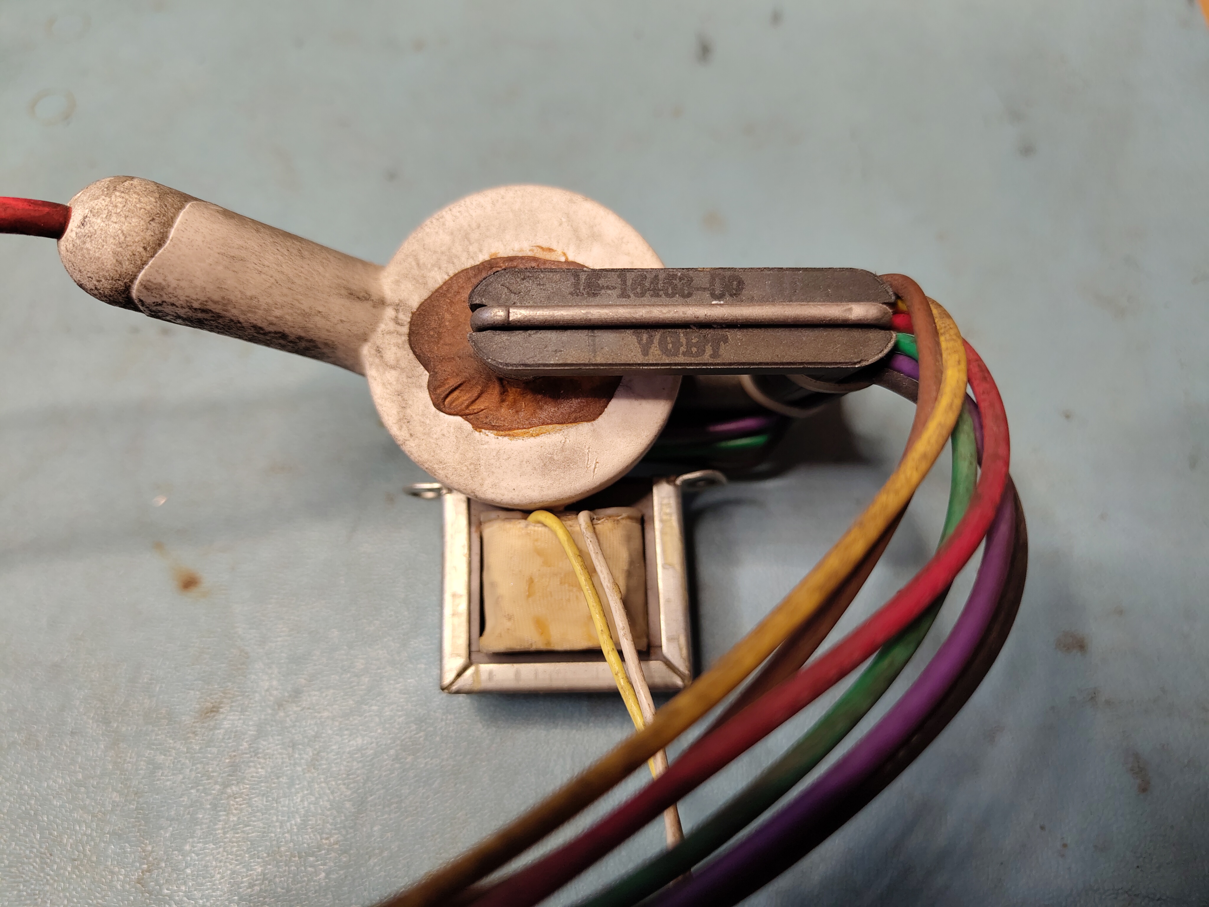
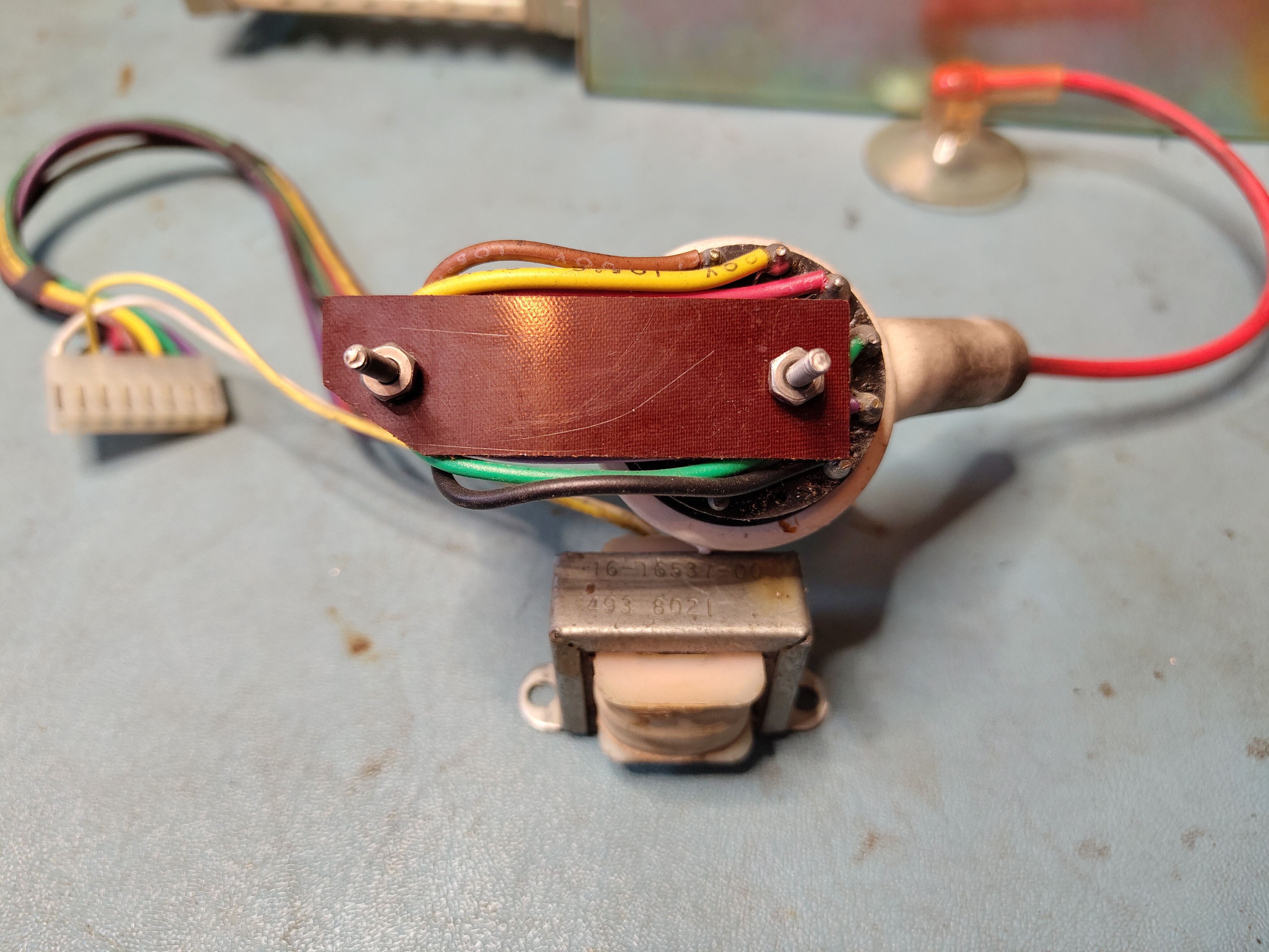
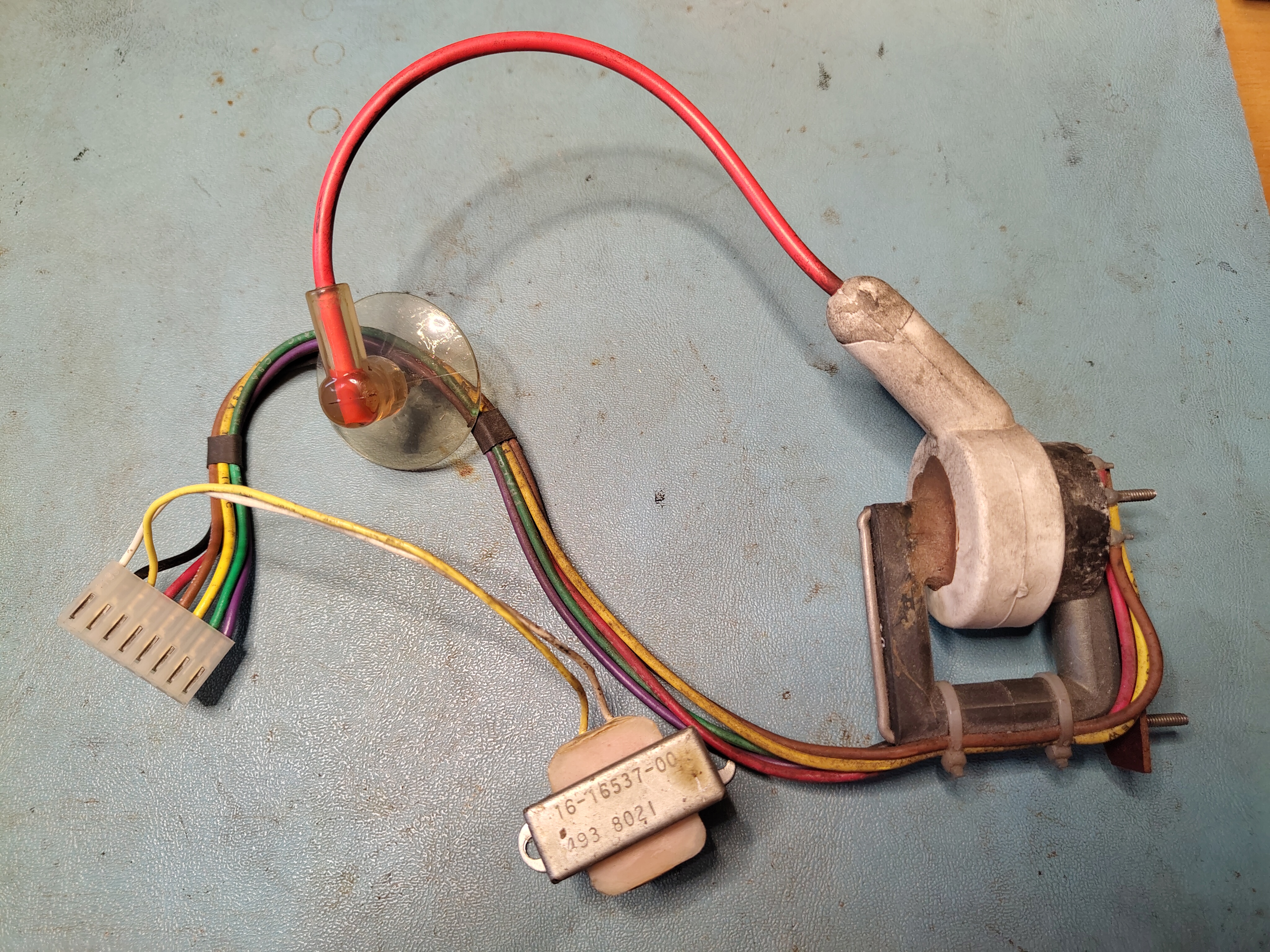
This is the failed flyback transformer, the part number is 16-16463-00:
So that is the end of that, I have to be content that I got it to work with the external video connector. My best hope is to find a replacement flyback one day from another VT100. It seems that making a new one is highly impractical.
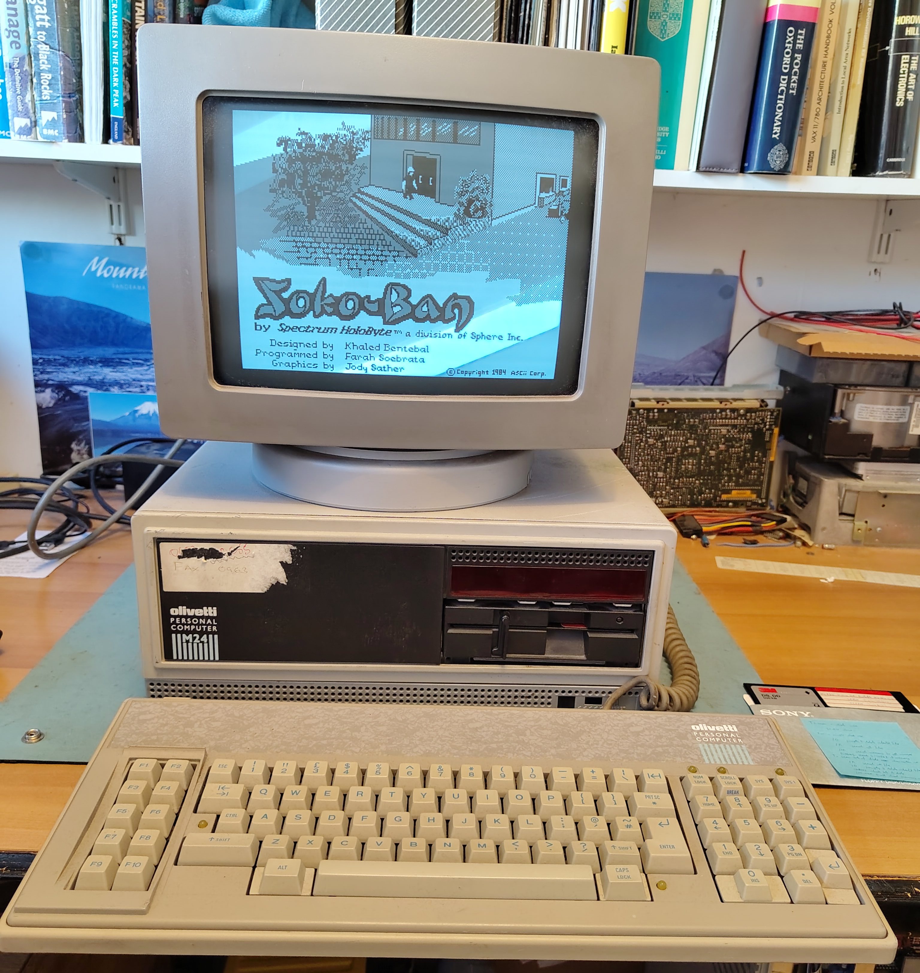
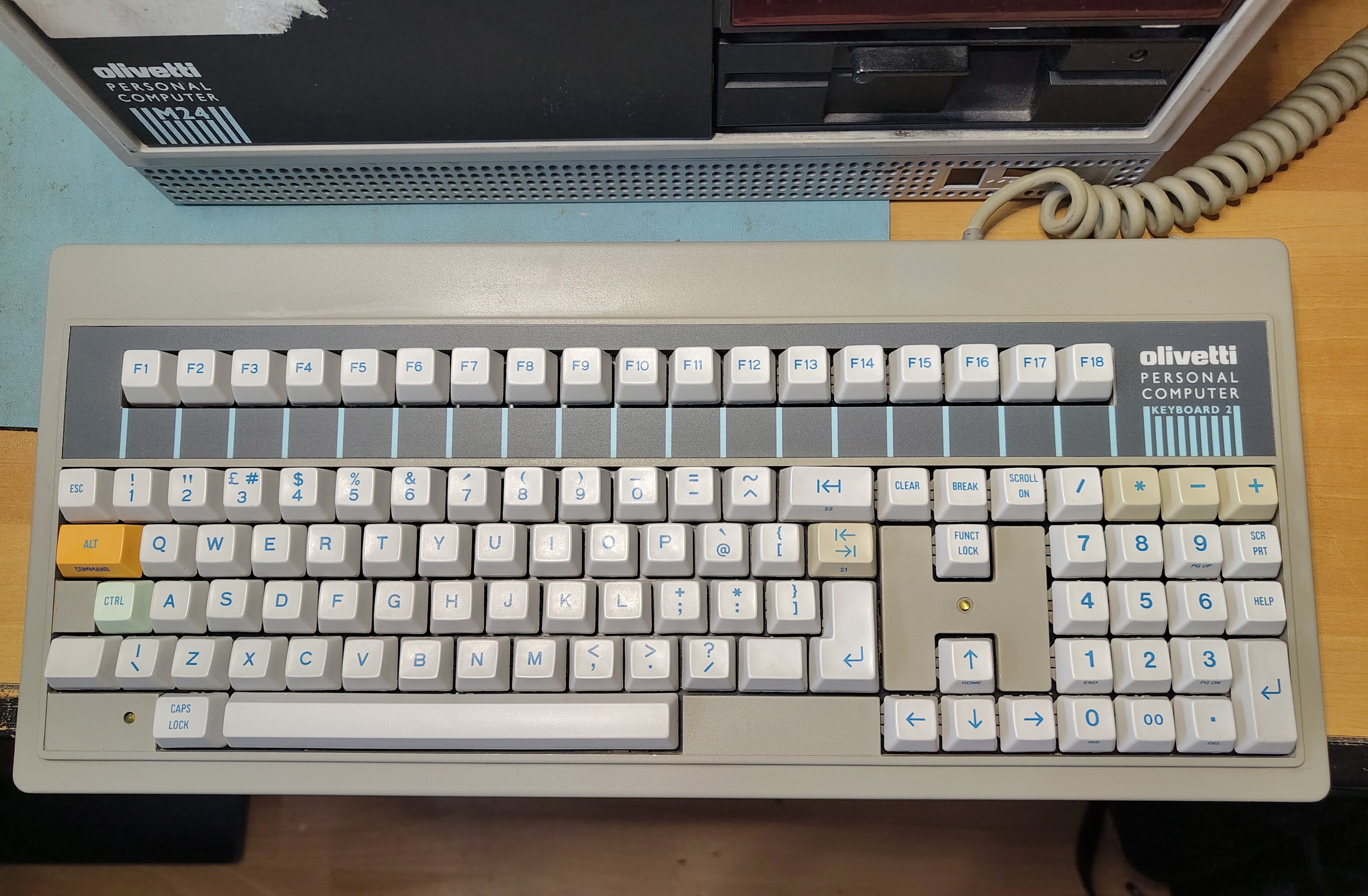
I have had two Olivetti M24s for a while, one with monitor and keyboard but no HDD controller and one just the base unit with a HDD controller but no drives, not even the floppy disk drive. Recently I acquired a second keyboard (ANK 2886). I got the keyboard partly because the original (ANK 2462) seemed a little unreliable, although it just turned out that it needed a bit of attention. I had put together a working system from the combination of the two machines and the machine worked nicely.
While using the machine I switched it off because I don’t like leaving vintage machines powered on while unattended. When I came back it would not power on. There were no lights on the front panel or the keyboard, and there was no display. Only the fan turned.
I suspected a power supply failure. It is an ALI LA16. I opened the case and checked the power in the Molex connector for the disk drives. The 5V pin was at 0V and the 12V pin was about 2V, this was with all loads connected. So clearly the power supply has failed. To get the PSU out I followed this procedure, all the orientations are facing from the front of the case:
Disconnect the power cable to the drives from the PSU.
Pull out the drive cage (use a screwdriver to lever away the locking mechanism on the underside of the cage).
Remove power, interface and earth wires from drive cage and remove the drive cage.
Remove the HDD controller (if too close to the PSU to reach the screw).
Disconnect motherboard power cables.
Disconnect the two 12V connectors on the left (they just pull out).
Disconnect earth wire from base at the front of the PSU.
Remove screw that holds down the PSU on its left.
Remove the fan cover (two screws at the bottom).
Disconnect the fan (I marked one of the connectors and took a picture so I can reconnect them the right way around).
Pull the PSU out.
To open up the PSU itself:
Remove the two screws at the top of the panel with the mains connectors and switch.
Remove the screw on the side panel that is not connected to the earth wires.
To remove the boards:
Remove the screws holding the earth connections at the side and at the connectors to the motherboard.
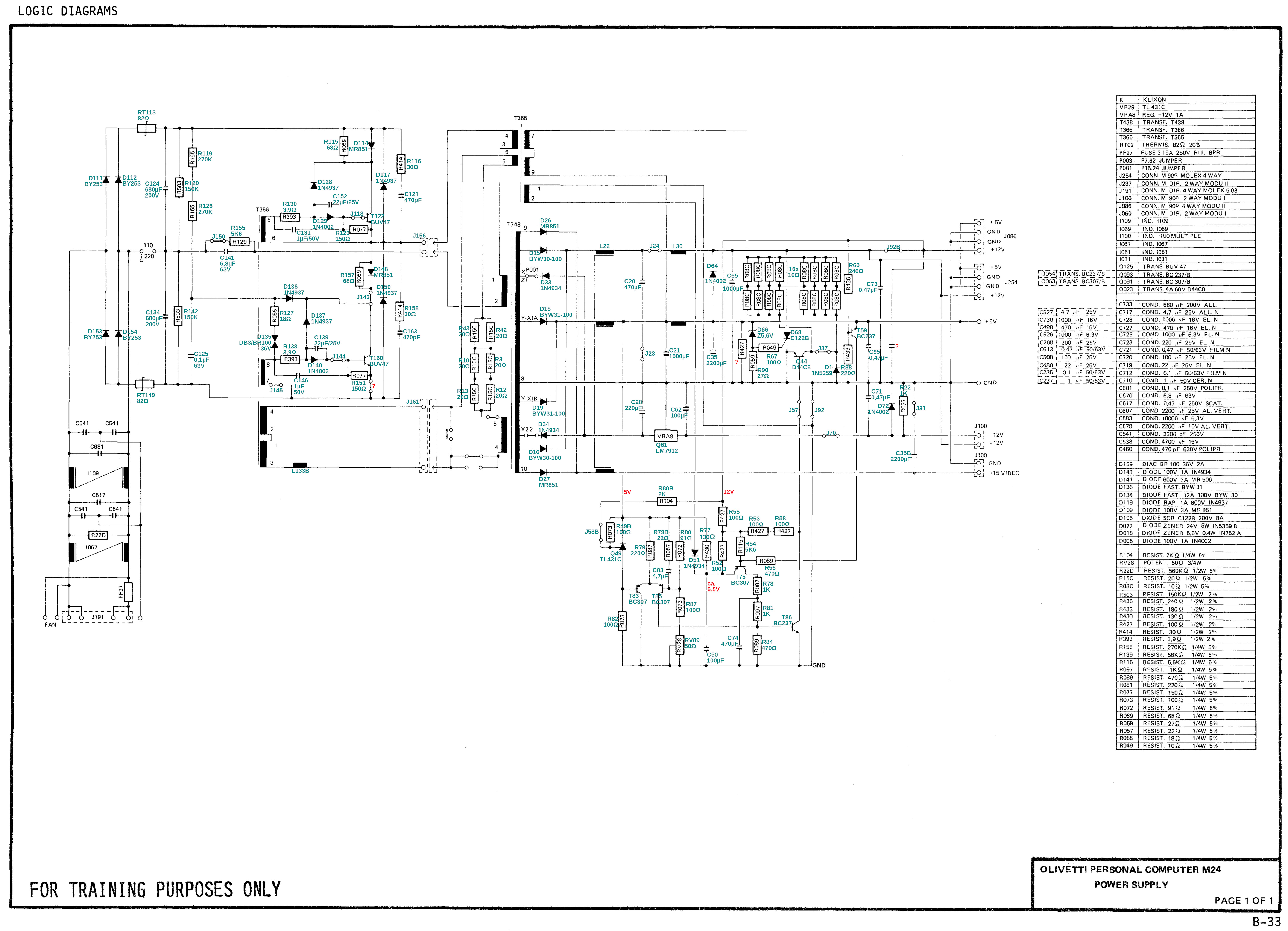
The schematic for the PSU is in the Theory of Operation manual, but the part numbers don’t match up to the markings on the boards, so someone on VCF has produced a marked up version which I have copied here for those who don’t have an account on VCF.
Note that there are a couple of errors:
R88 is 180R, not 220R
C21 is 10,000uF, not 1,000uF
During my work at trying to find and fix the fault I found that sometimes the PSU would actually work, but then at other times the outputs would stay resolutely at 0V. Also, while trying to test different parts, I noticed that one of the connectors for connecting between the two boards was loose and actually came away. I think this might have been marginal and in my attempts at separating the two boards it finally came away. I re-soldered it, but the PSU still wasn’t working reliably.
I tested the capacitors C21 and C35 on the +5V output and found that they seemed to measure inconsistently and one seemed to have a barely discernible bulge. I decided to replace them. When I replaced them the PSU started to work. However, in testing further, I found that the PSU did again stop working, but leaving it alone for a while seemed to clear it up. It feels like it is working better but almost certainly not fully fixed. For now it seems to work reliably, and I have had no further failures.
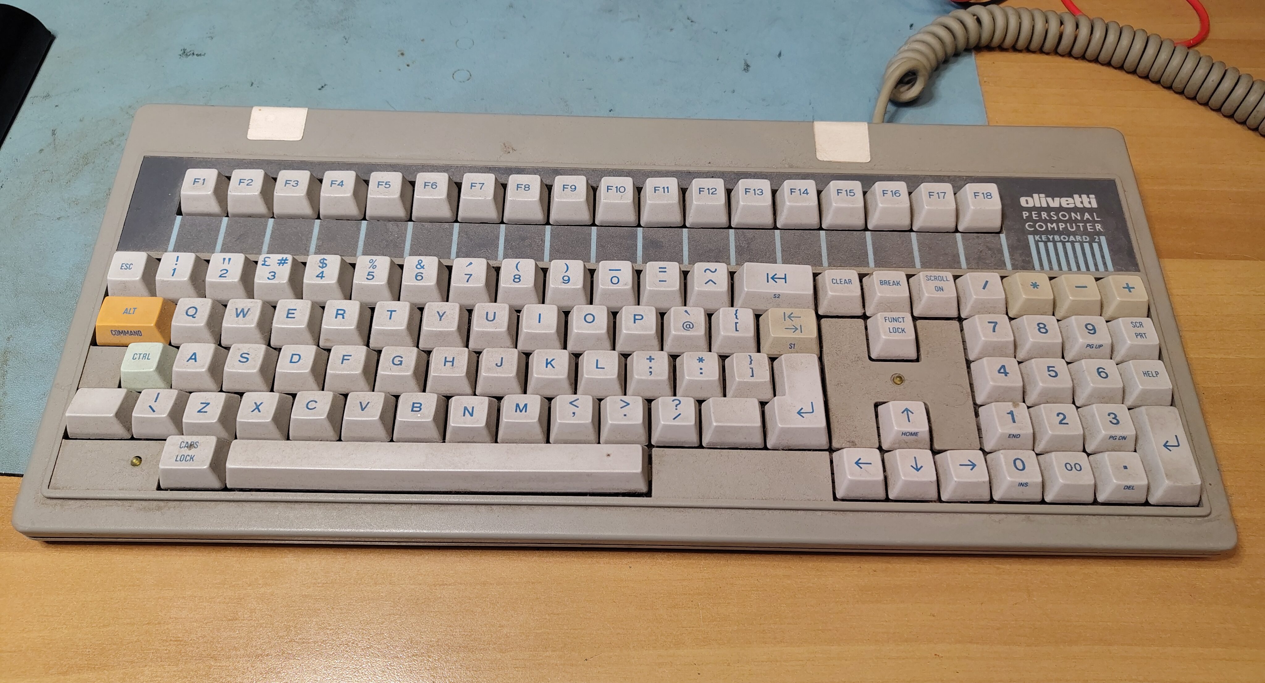
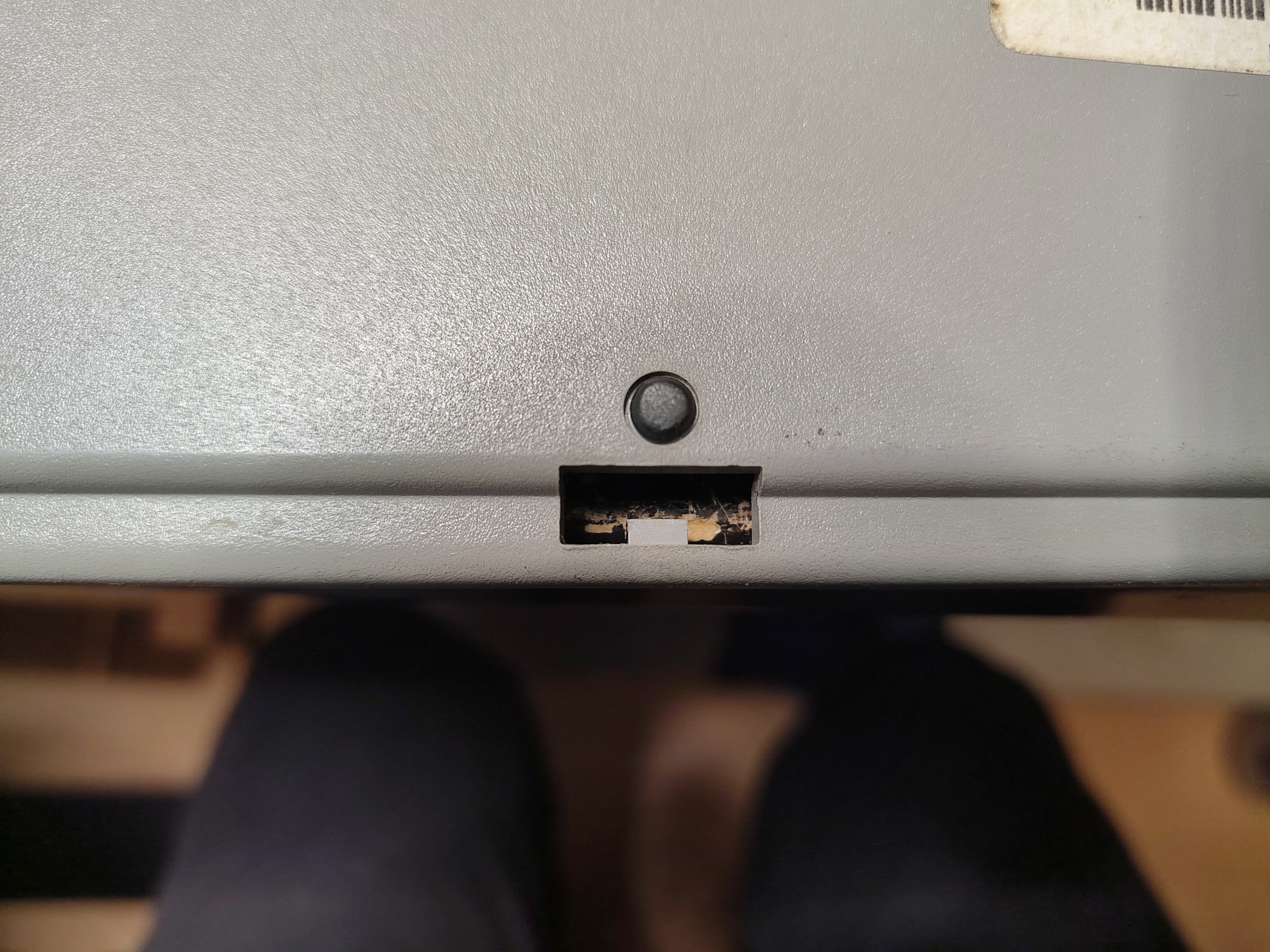
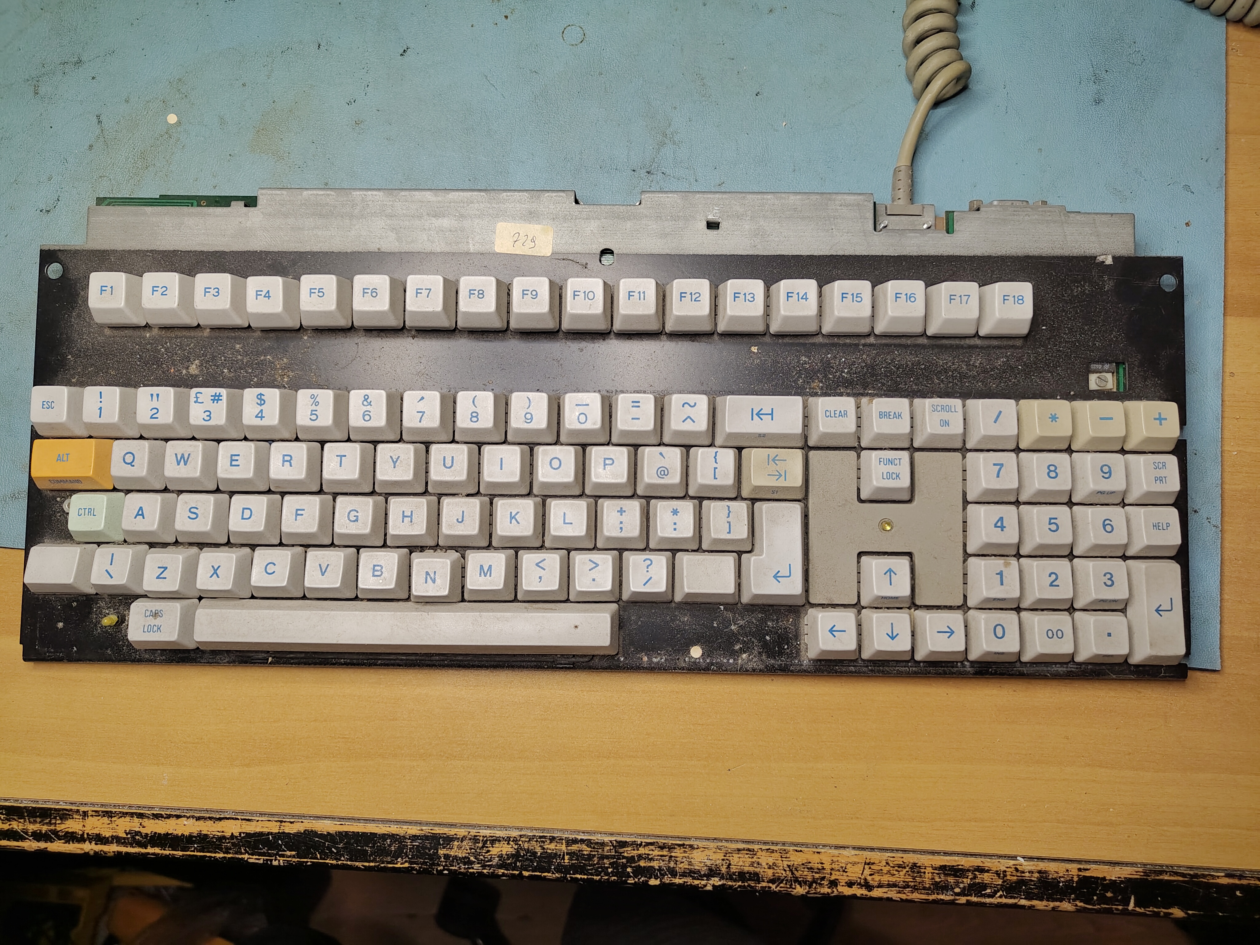
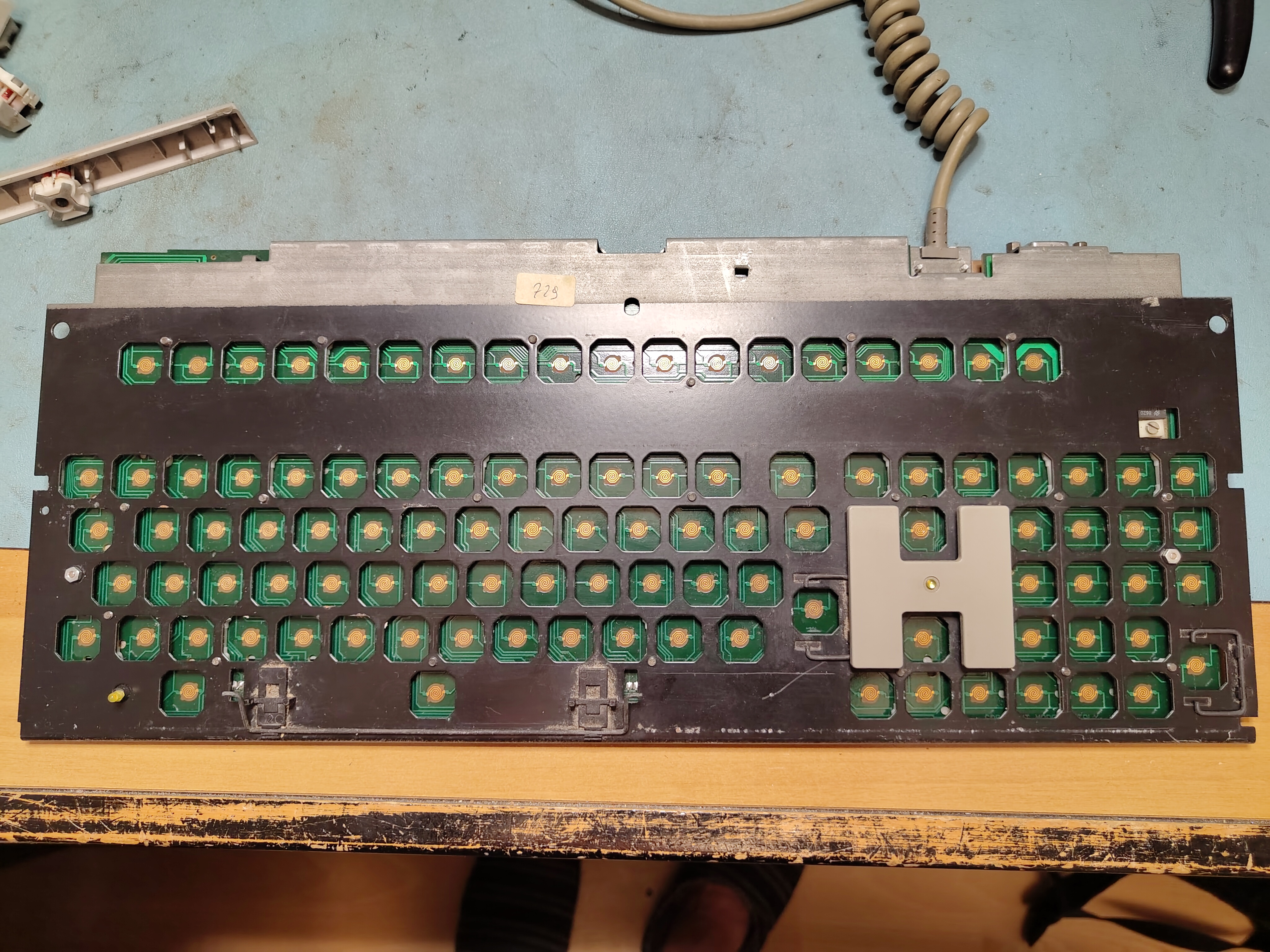
When I acquired my first M24 it came with a keyboard. I had found it to be unreliable with some of the keys needing to be pressed multiple times before they were registered, and the enclosure was held together at the back with some tape because two of the retaining lugs have broken off. This is how the keyboard looked:
Olivetti M24 ANK 2462 Keyboard Before Restoration
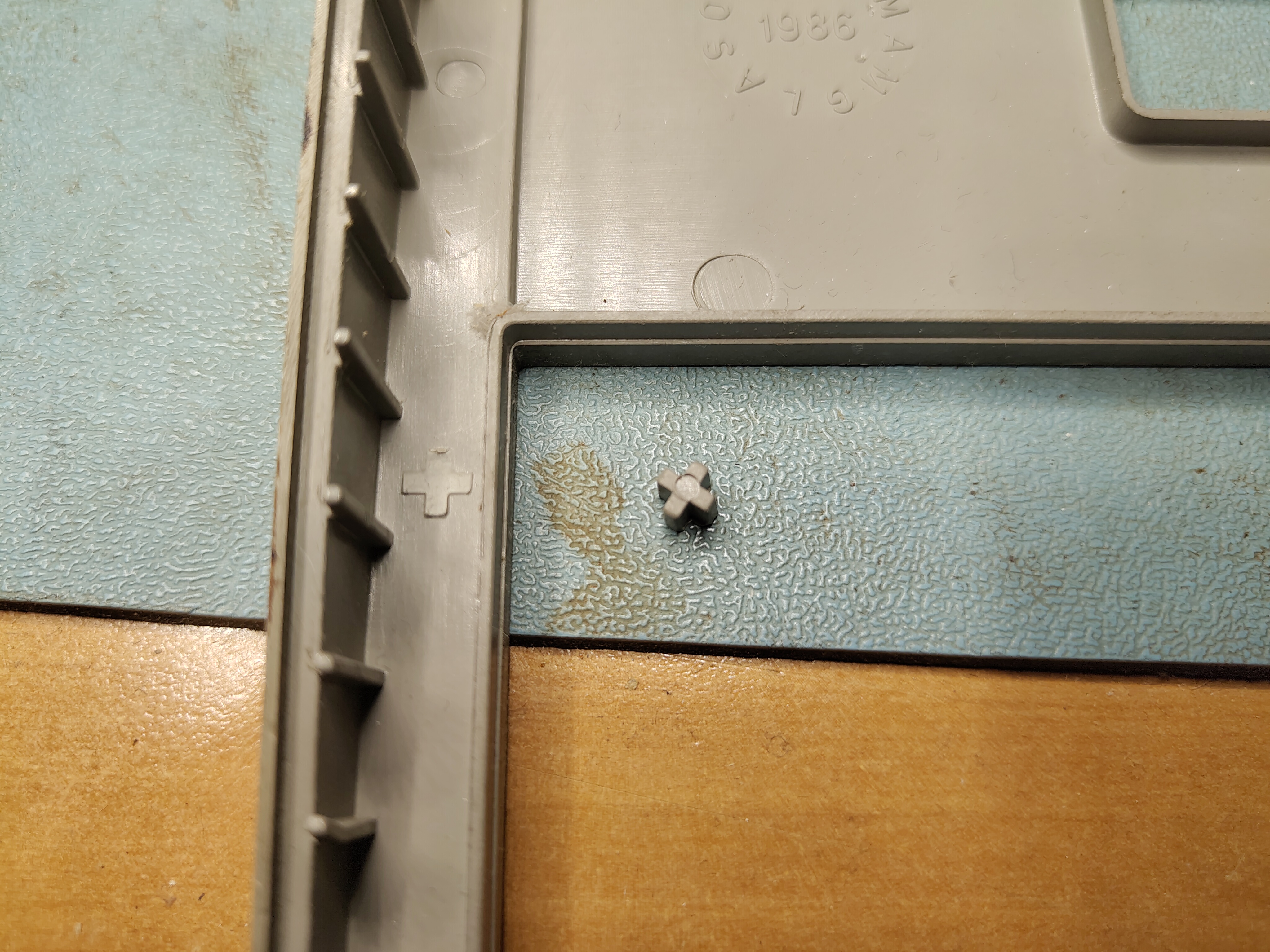
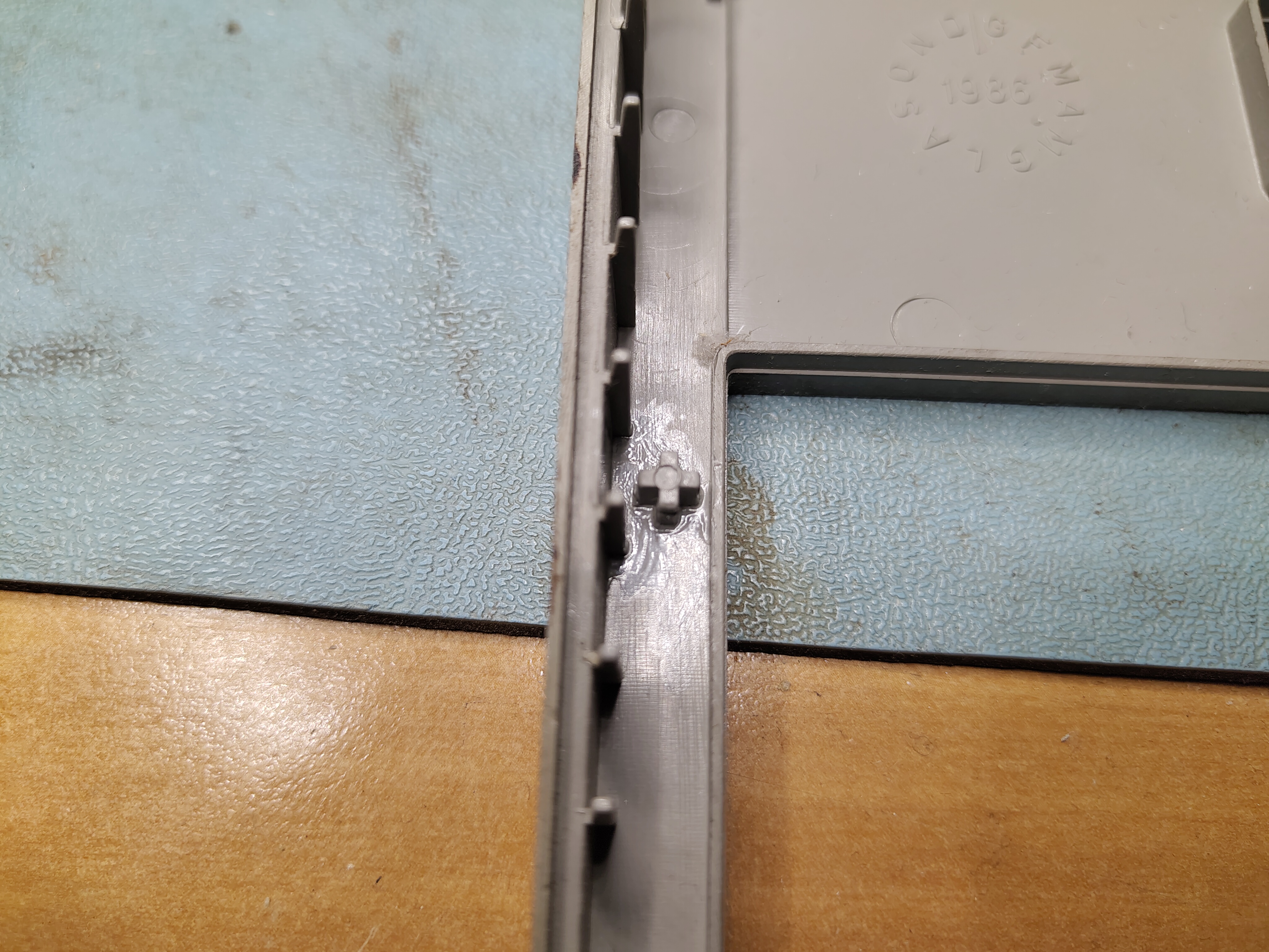
It proved quite easy to take the keyboard apart. There are clips on the underside that can be carefully prised open with a screwdriver, but two of them at the back didn’t work because the retaining lug had broken off. I also managed to crack one of the clips, but some Pro Weld seemed to fix that.
One of the Lugs That Holds the Keyboard Together
I also found that a small lug had broken off elsewhere and I used Pro Weld to glue that back on too.
Broken LugBroken Lug Glued Back
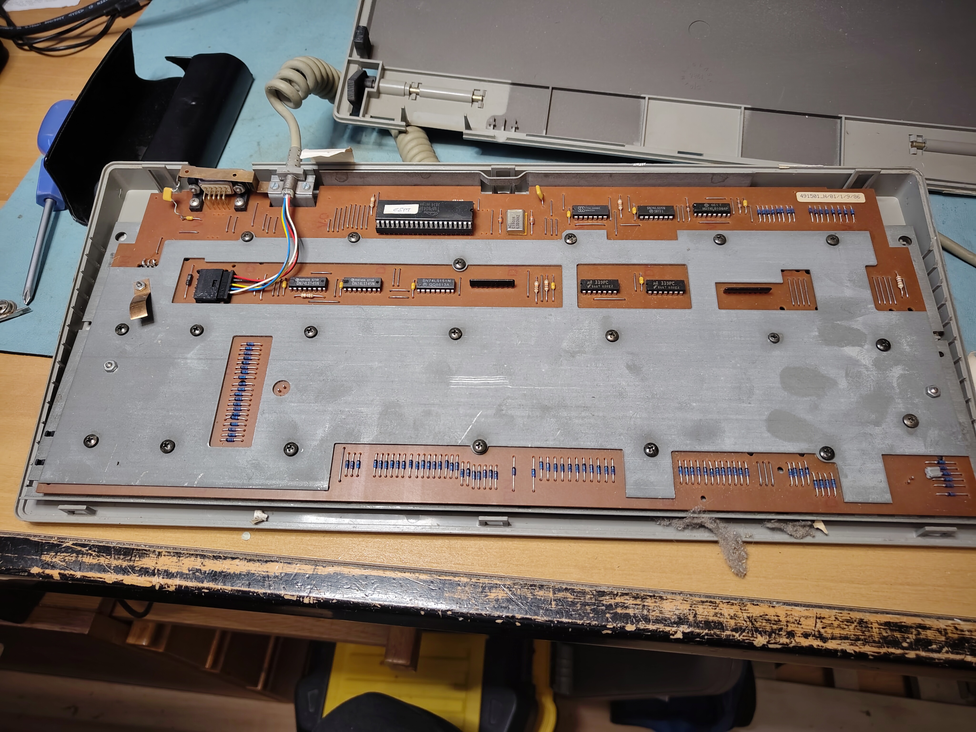
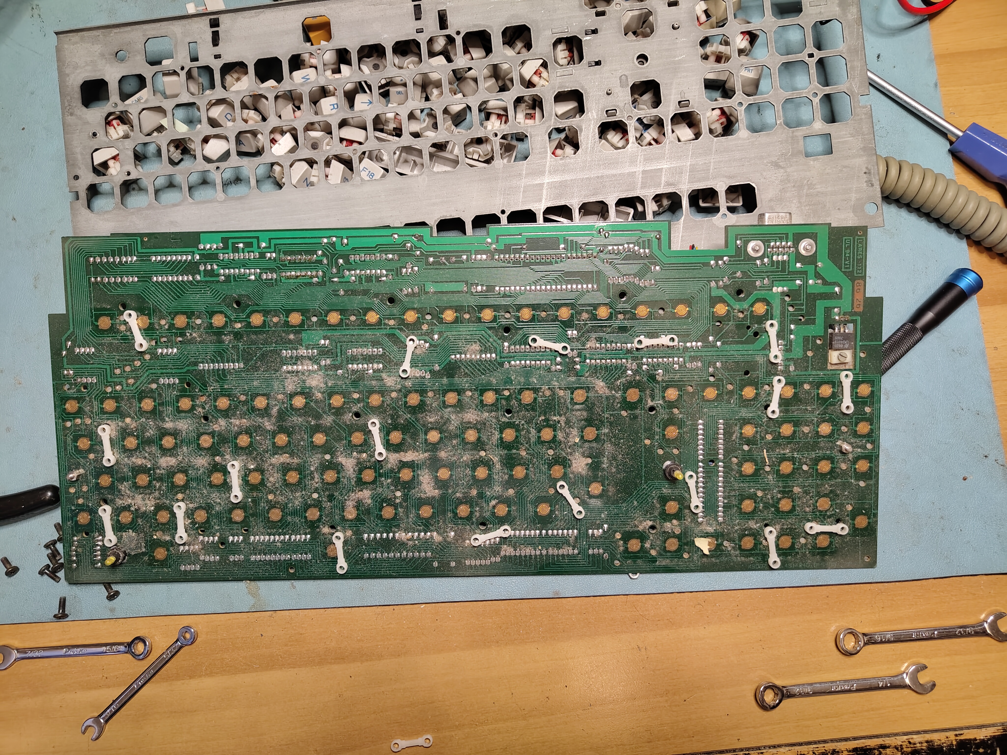
With the enclosure removed the underside looks like this. There are 20(!) screws holding the front plate in place, and there are plastic spacers between the front plate and the PCB so that the front plate can be used to clip the keys into place.
Underside of the Keyboard PCBKeyboard After Removal From Enclosure
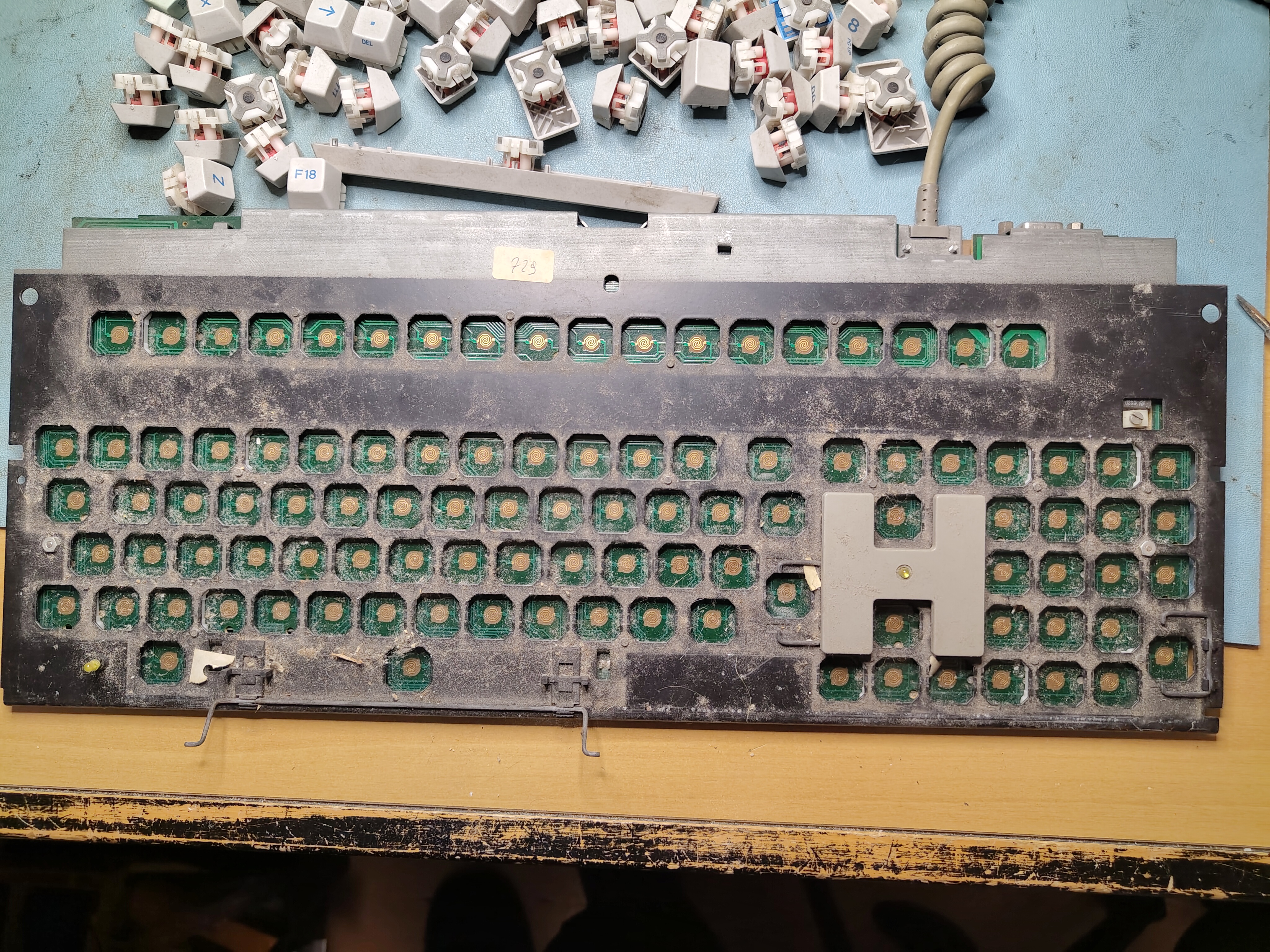
Once the keyboard was out I removed all the keys. This was easy as they are retained with some simple clips that can be gently levered with a small screwdriver. The clip had broken on one of the keys, which made it a little harder to get this one out. With all the keys removed it was evident that the keyboard was quite dirty.
All Keys Removed
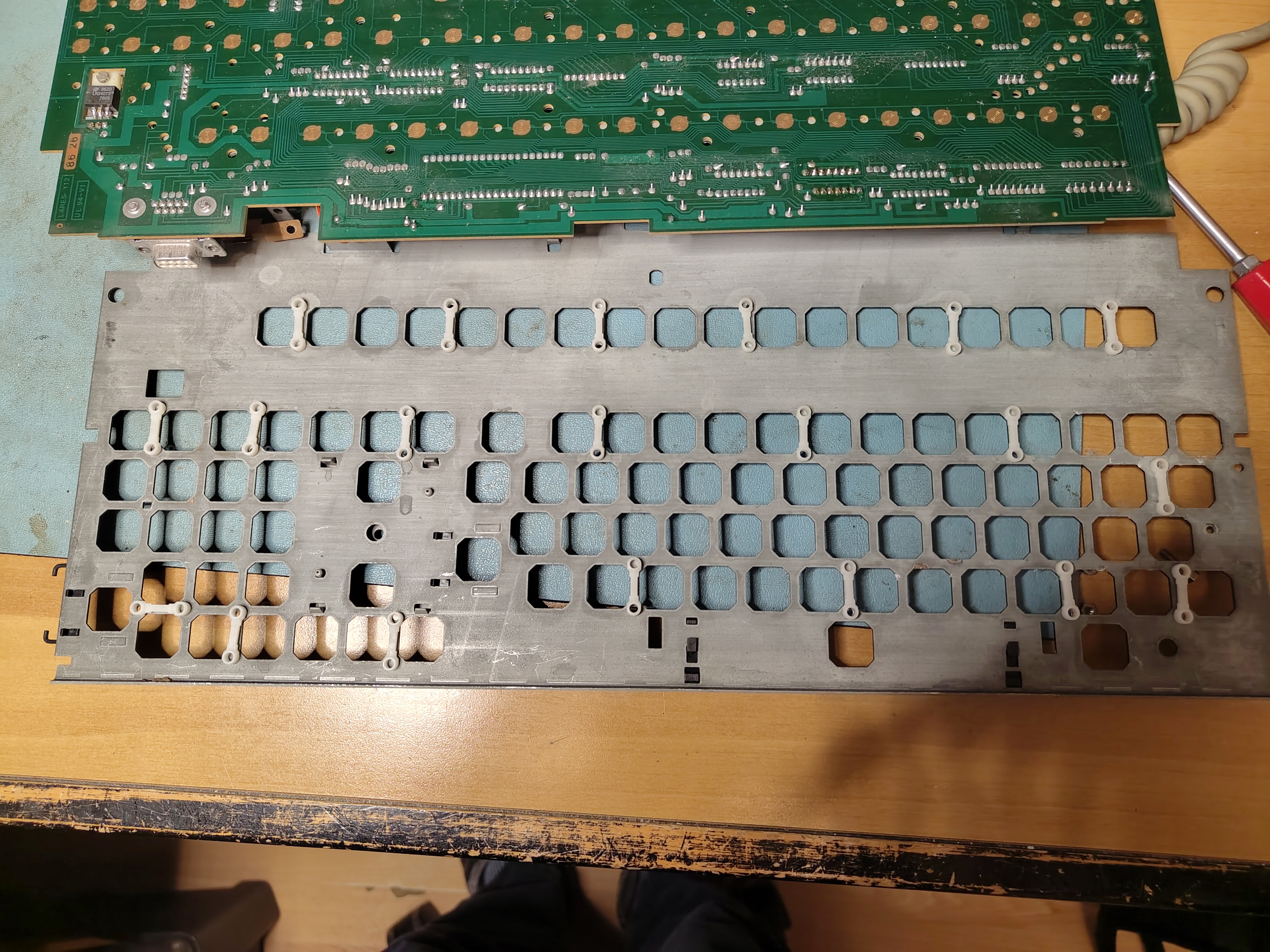
After unscrewing the 20 screws and two nuts, removing the front plate showed the spacers, which had moved.
Front Plate Removed Showing Plastic Spacers
I found that there were marks on the back of the front plate that made it easy in most cases to find where the spacers went.
Spacer Locations
I then set to work with isopropyl to clean the PCB and the front plate. I didn’t clean the entire front plate as I didn’t want to remove the clips for holding the larger keys in case I broke something.
PCB and Front Plate After Cleaning
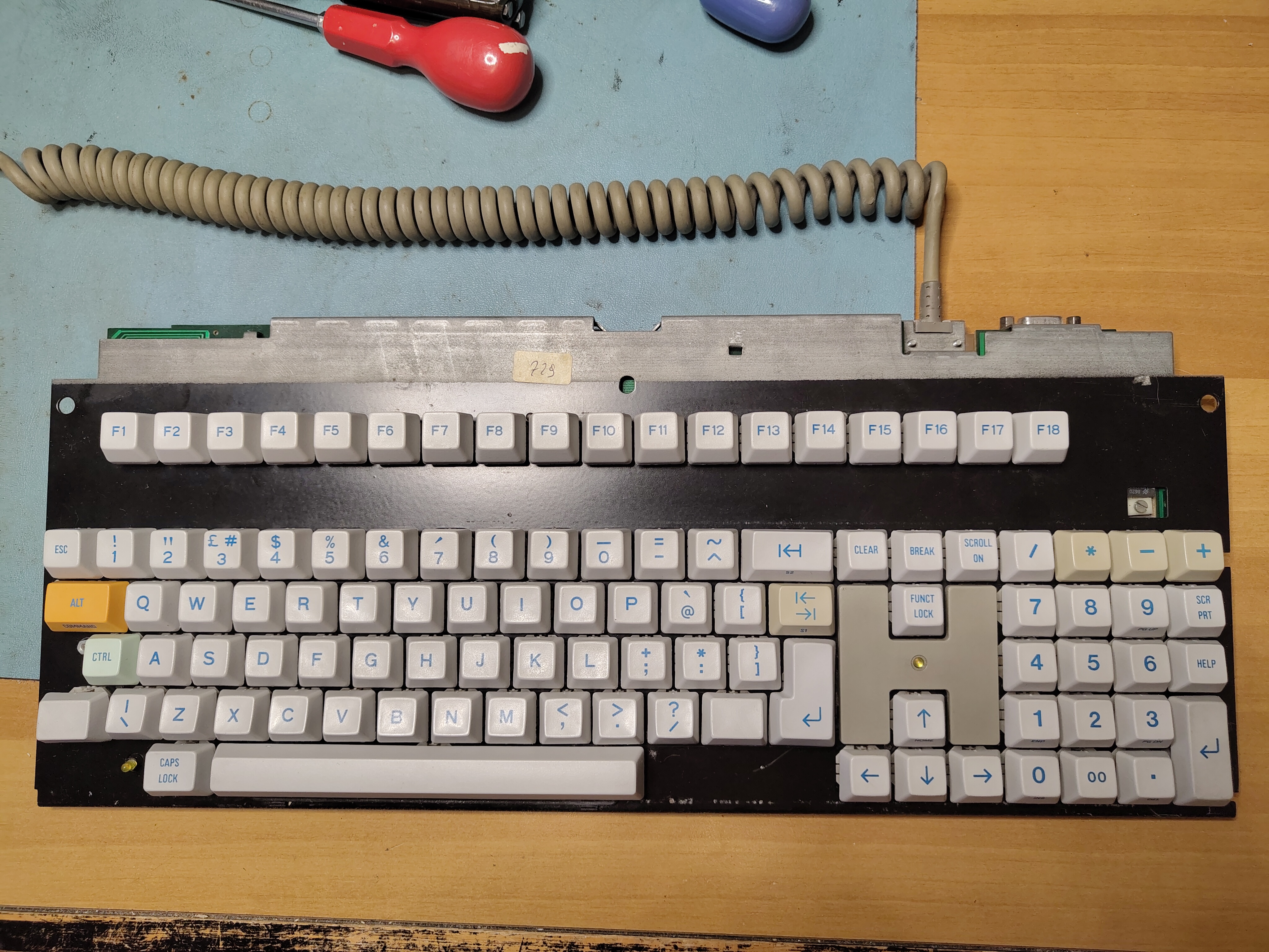
Next I cleaned all the keycaps and cleaned the contacts with isopropyl. I put back the keycaps and tested the keyboard before remounting it in the enclosure.
Keyboard Ready for Testing
The M24 comes with a Customer Test diskette which includes a keyboard test. I found a couple of keys were still not quite right, and I re-cleaned the contacts on the PCB and the keys themselves, and they started to work reliably.
Once all the keys were working property I cleaned the keyboard cover and reinstalled it. I removed the glue residue from the tape that had held the enclosure together where the retaining lugs had broken and then used some duck tape, more discreetly applied, to hold together the enclosure where the retaining lugs are missing.
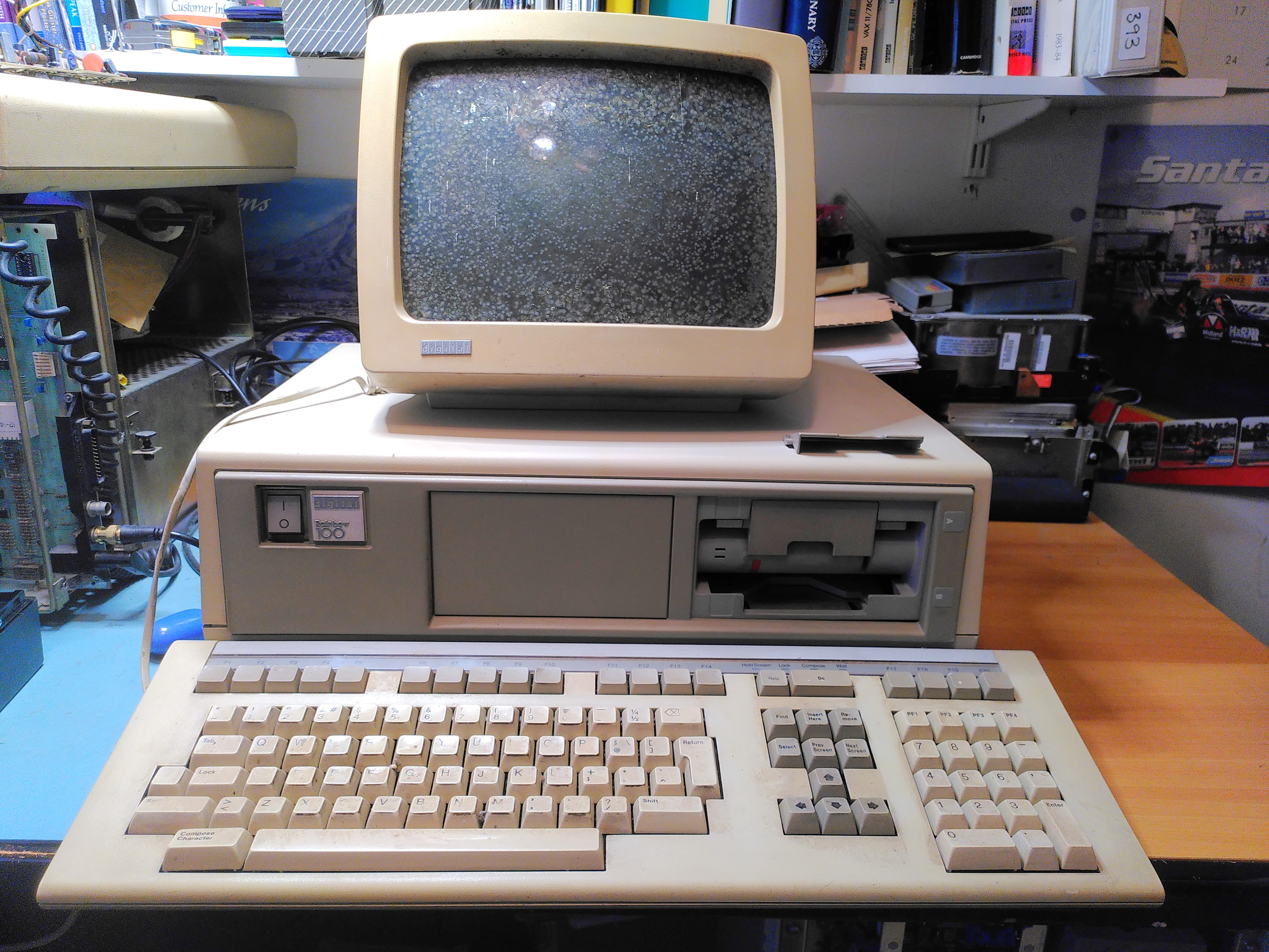
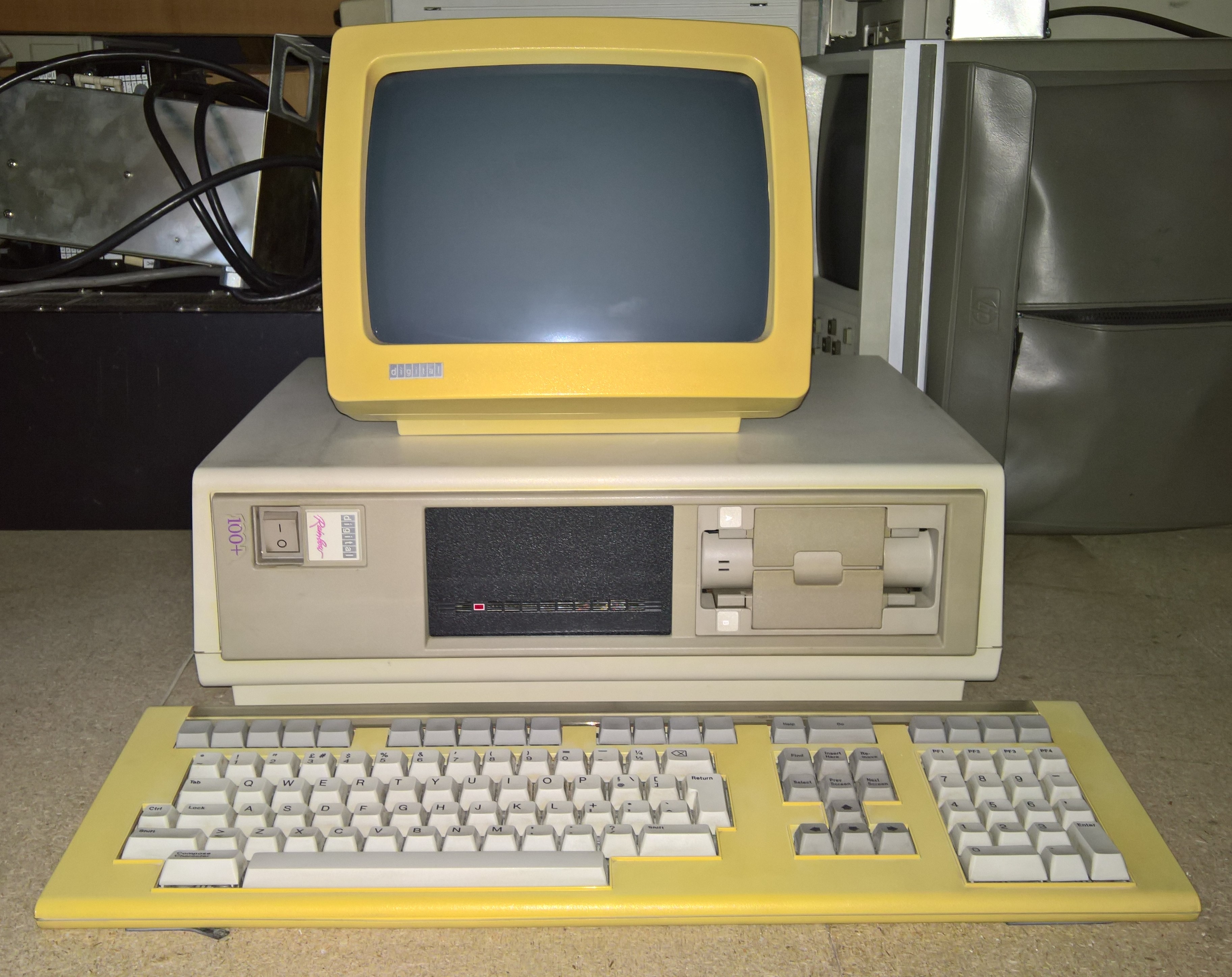
I acquired a Rainbow 100A a while back. It had a few problems:
Video RAM fault.
Screen cataracts.
RX50 floppy disk drive door adrift.
RX50 would not read disks
Rainbow 100A as Received
It also came with a Floor Stand, an LA50, manuals and disks.
PSU Inspection
Before switching it on I checked the PSU visually, mainly for any bulging or leaking capacitors. Once I was satisfied with this I was able to power it on. I checked the ripple on the power supply, that looked fine too.
Video RAM Fault
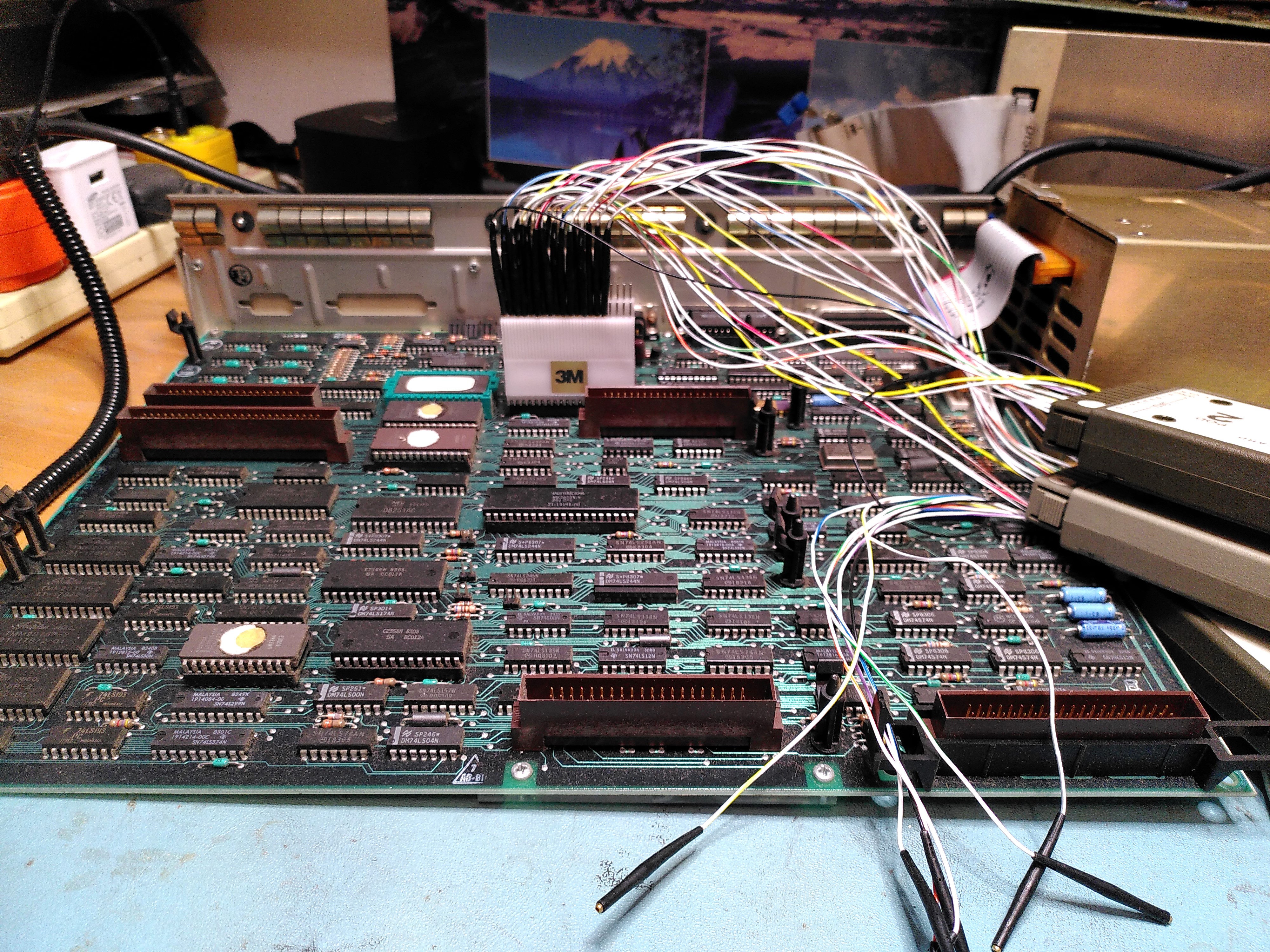
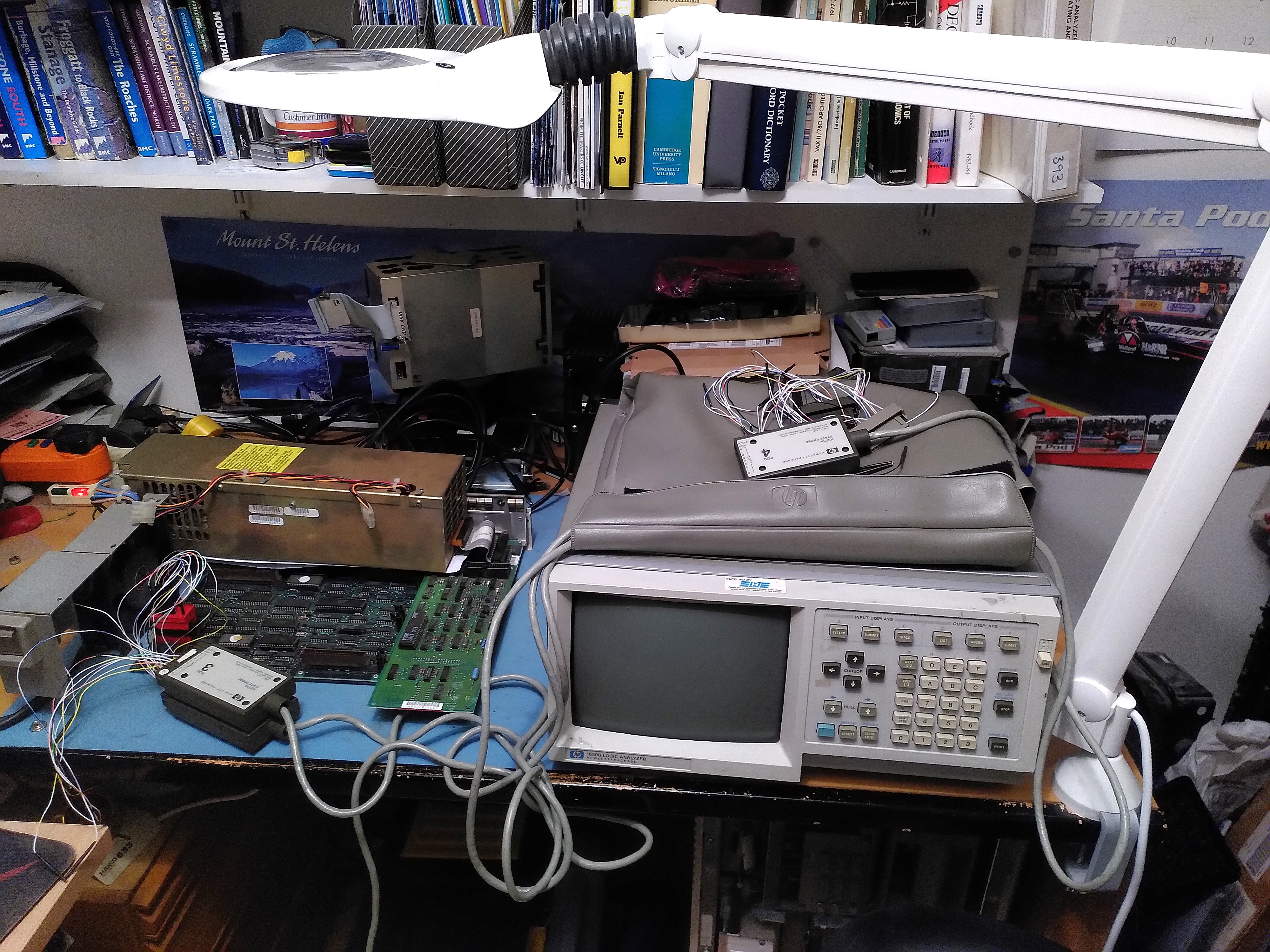
The diagnostic LEDs on the back were showing the code 1110110 indicating a Video RAM fault. After a few sanity checks I got the logic analyser out. At first I put the probes on the RAM chips themselves (E121-4). It looked like it was only writing to addresses 0 and 1 of the lower 2K of the screen RAM (chip E122).
Logic Analyser on the Rainbow 100A 8088 MicroprocessorLogic Analyser on the Rainbow 100A Screen RAM
As I was not confident of my ability to capture the reads and writes on the RAM I decided to try to get an address trace from the 8088 microprocessor instead. There I could be more confident that I was triggering on the correct signal (negative edge of ALE) to capture the addresses. I could not however tell if the addresses were reads or writes. After triggering on the Video RAM address range I confirmed that it was only accessing addresses EE000 and EE001.
To be doubly sure I got the system board out of another Rainbow (a 100B) and did the same thing. There I saw the Video RAM being tested with addresses being accessed in descending order.
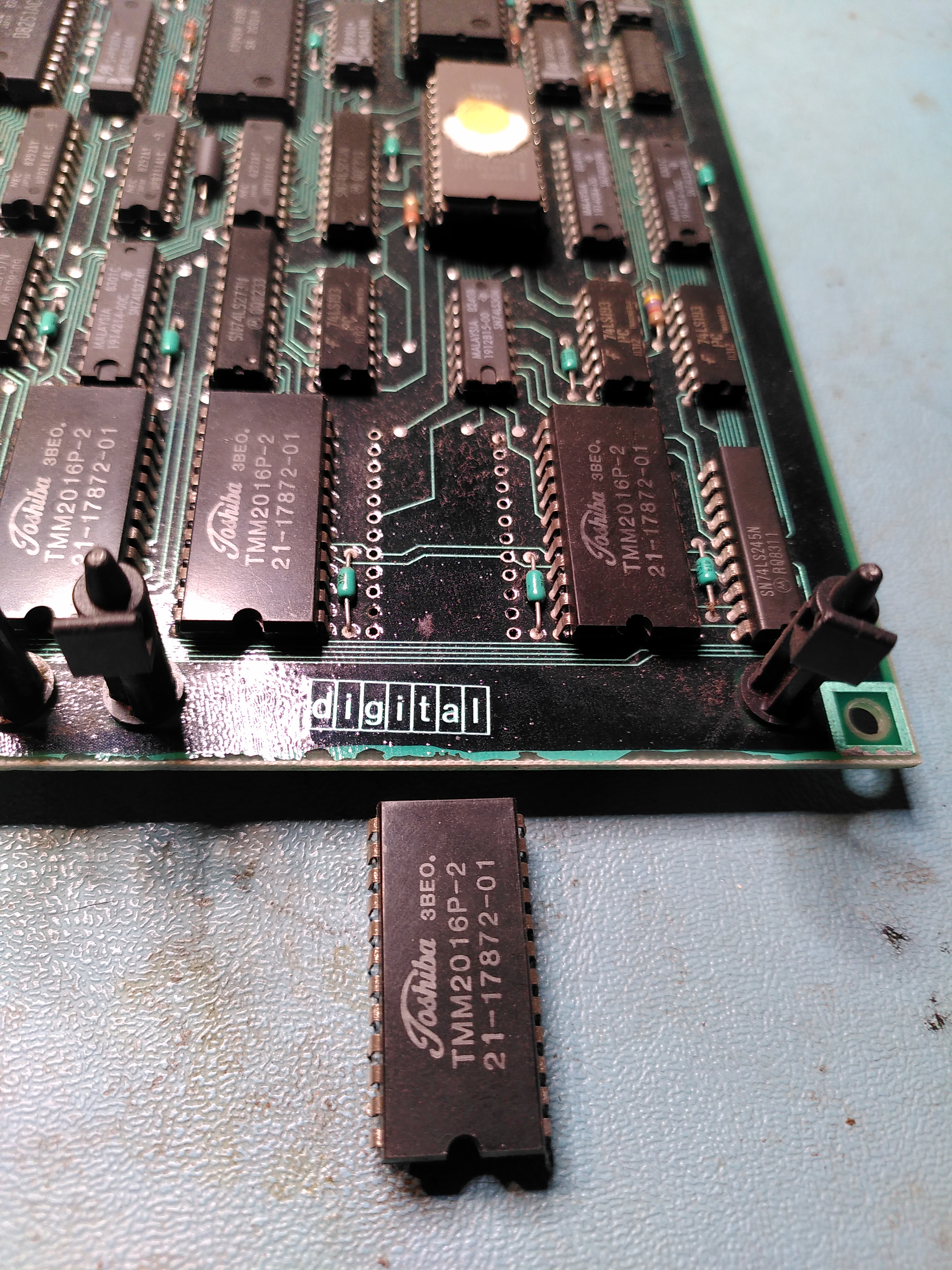
I decided that E122 must be faulty. This is a TMM2016P-2, I found a replacement marked TMM2016P, with no suffix. I don’t know if the replacement is a higher or a lower spec. However I replaced it.
Faulty Static RAM Removed (E122)
After doing this, with the system board still on the bench, with no floppy disk controller and no monitor connected, the diagnostic LEDs showed a lot more activity, finally settling on the code 0110101. This is Message 1 “Main Board Video”. I speculated that this could be because the monitor was not plugged in. So I connected a VR201, although not the one with cataracts. Sadly it displayed the same message.
Video Fault After Fixing Bad Screen RAM
This was a bit puzzling because it is obviously good enough to display a message.
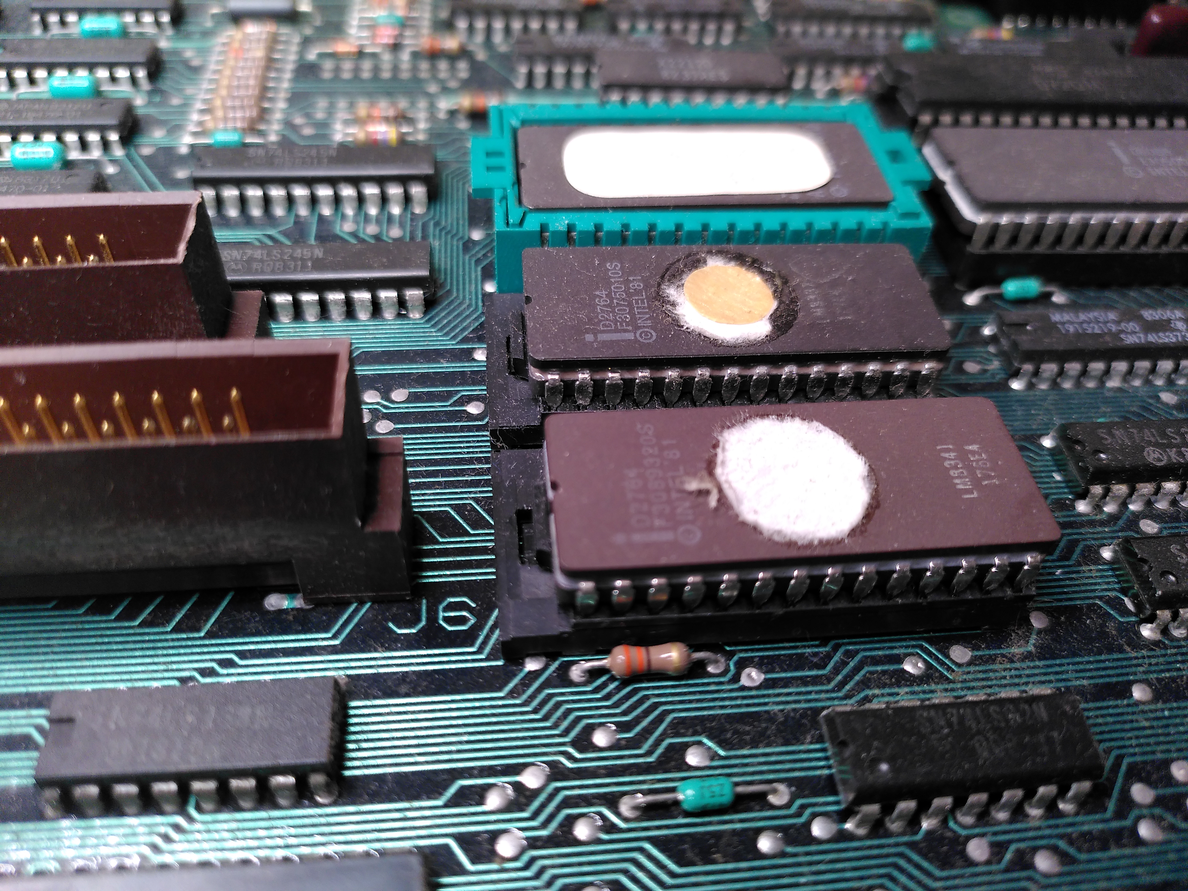
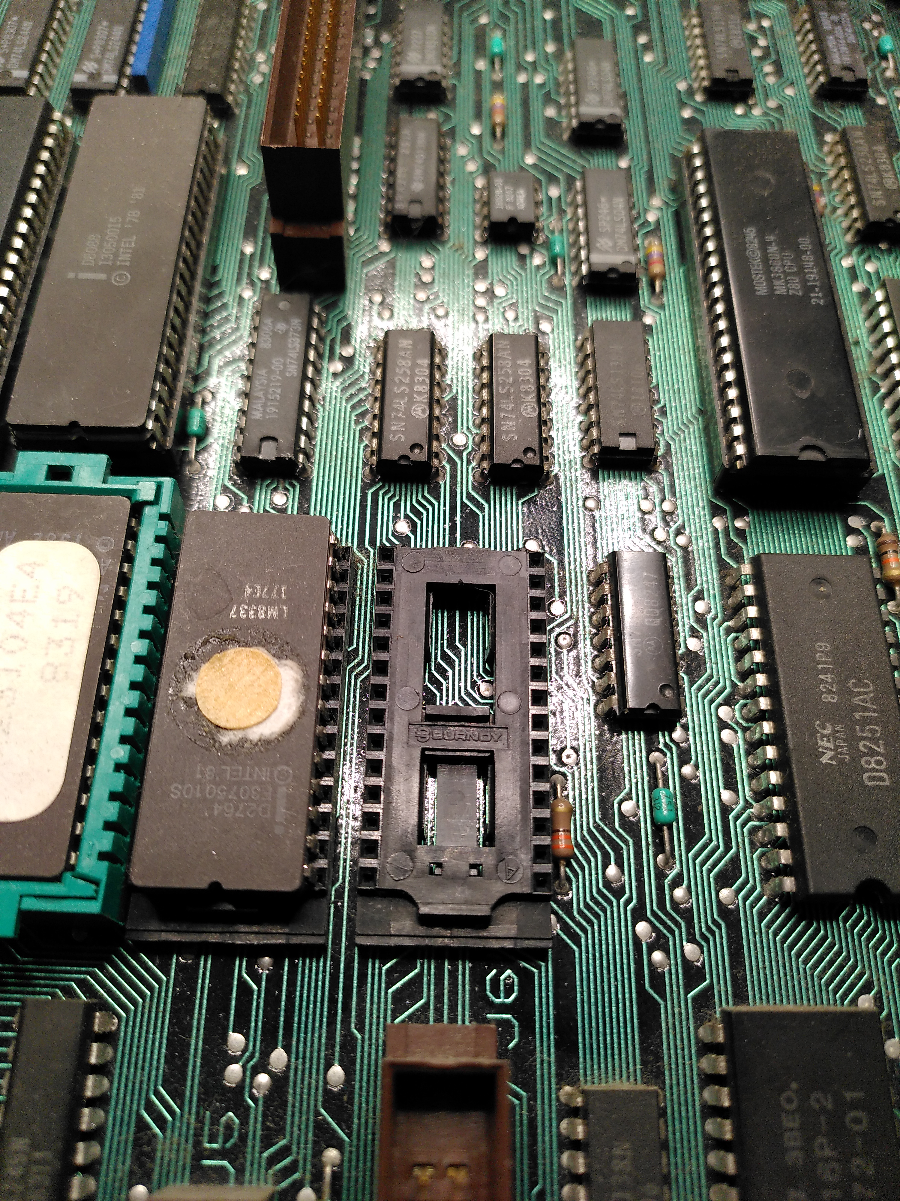
I decided to check the ROMs. This was a lot harder than I expected because the ROMs are mounted in a QIKEJECT socket. At first I didn’t know how to remove it despite a diagram in the Technical Manual. I realised that you need to put a screw driver in the slot and gently push down to release a clip, this allows the chip to be moved across and then it can be lifted out.
The ROMsQIKEJECT Socket Without the ROM
I checked the ROM with my programmer and the contents matched those of an image I found at archive.org.
Putting the ROM back was another story. I could not get the socket to move back to the locked position with the ROM inserted. It would move back when the ROM was not inserted, but there was nothing I could do to persuade it to lock with the ROM inserted. I asked on the forums at Vintage Computer Federation and it seems to be a common problem. So I de-soldered the socket and replaced it with an ordinary socket.
The Underside of a QIKEJECT socket
Because of the difficulties with the socket I decided that for now I wouldn’t check the other ROMs.
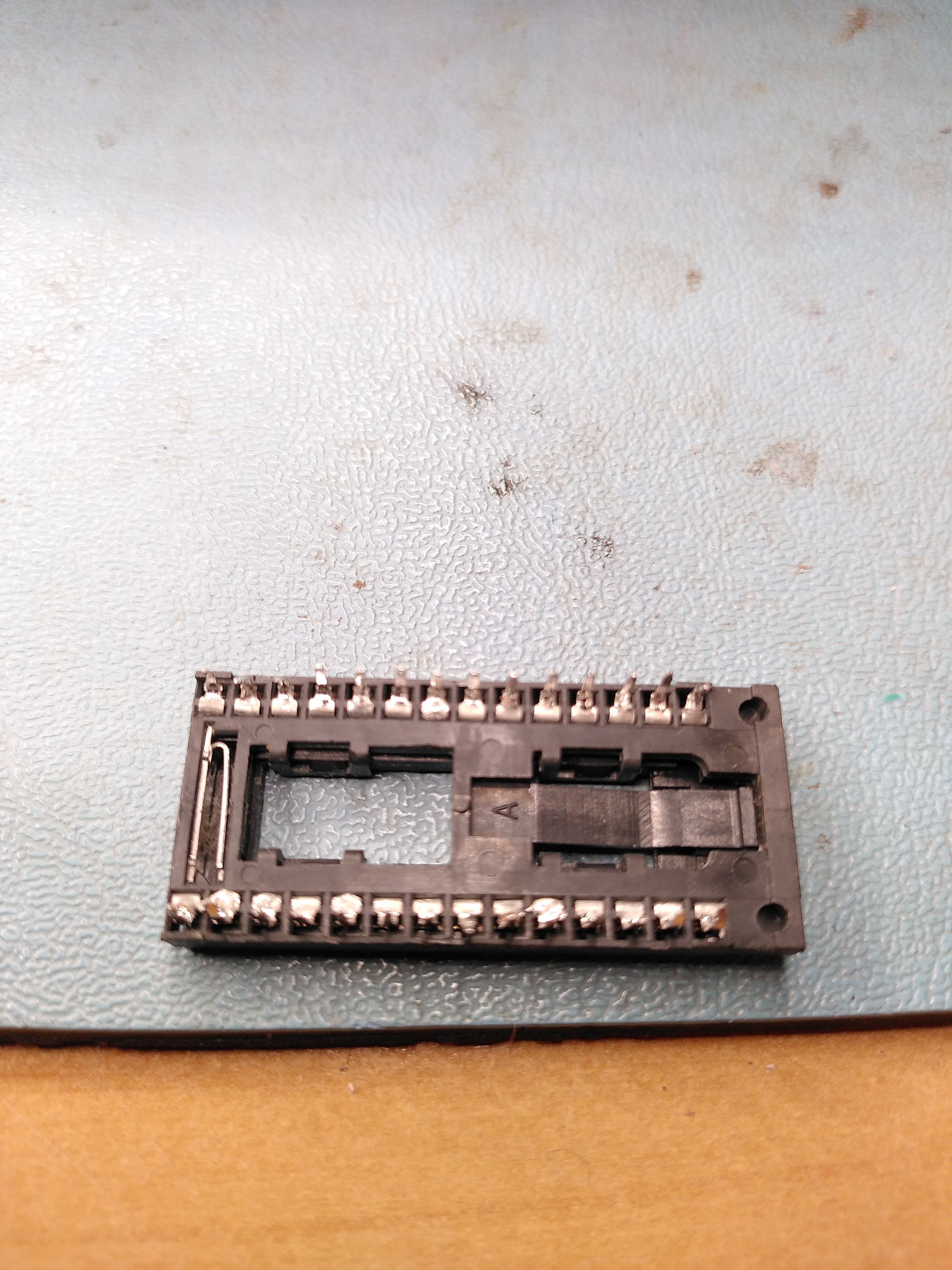
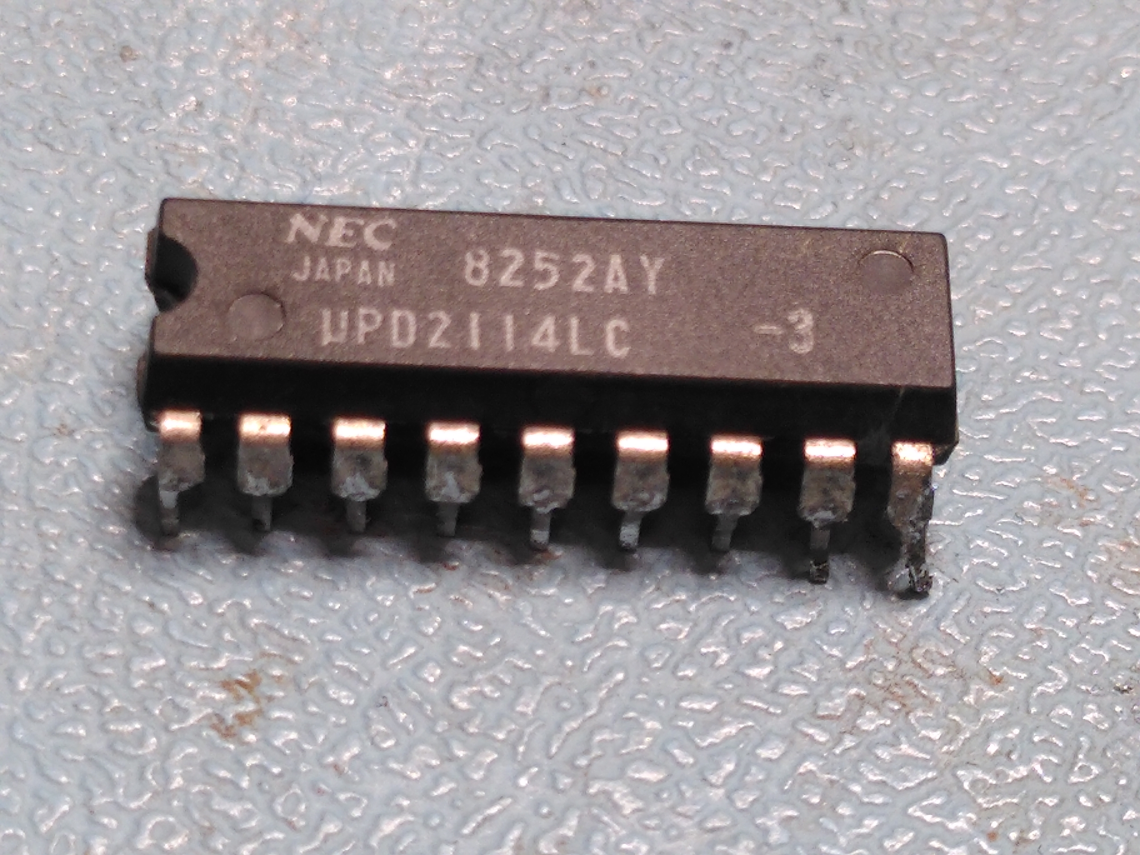
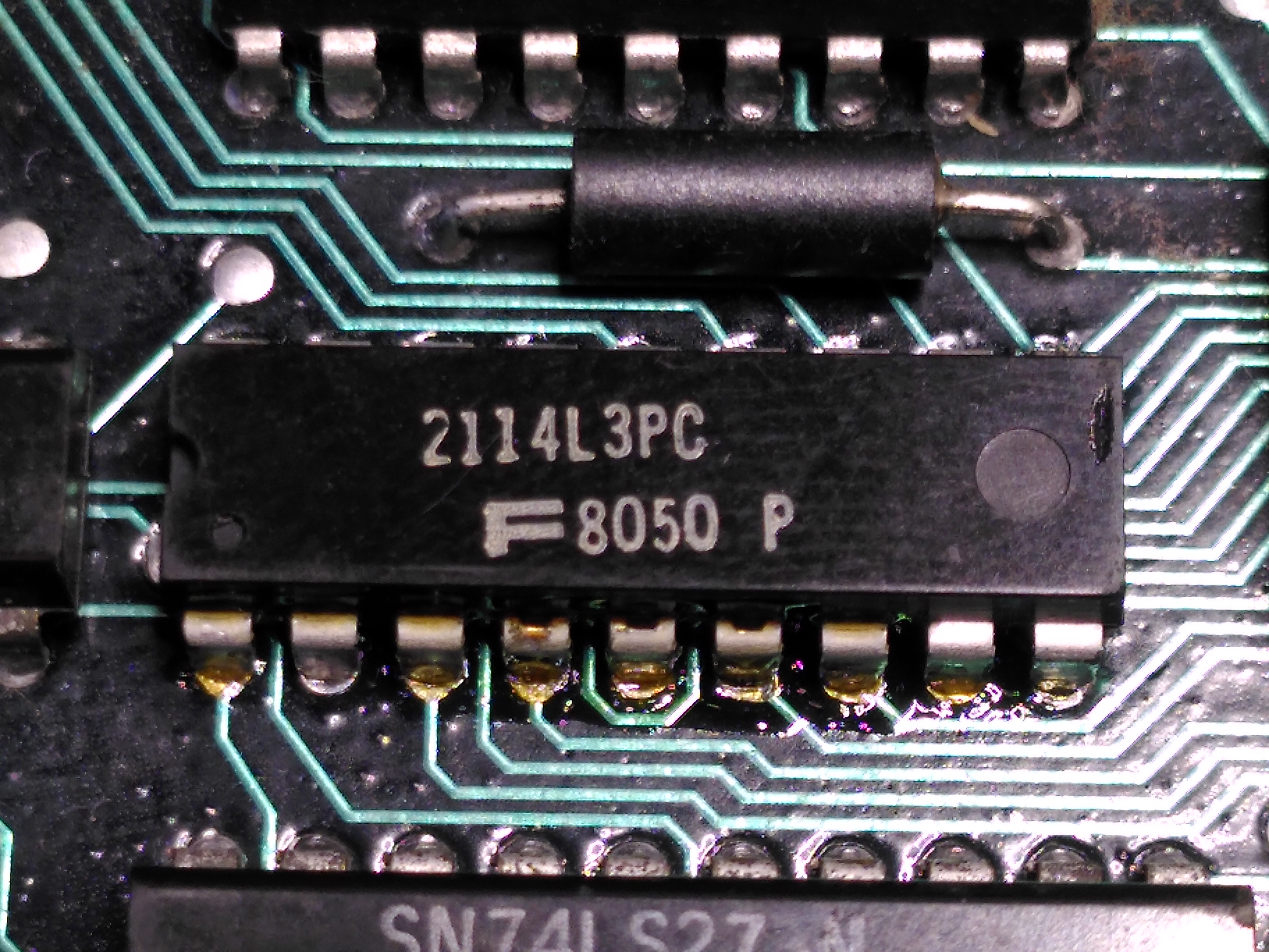
After a lot of work with the logic analyser, following the attributes from the Attribute RAM, through the Line Buffer and into the DC012 I finally discovered that one of the Line Buffer chips was not working reliably. This is a 2114 static RAM labelled E100 on the schematic.
Faulty Line Buffer ChipReplacement Line Buffer Chip
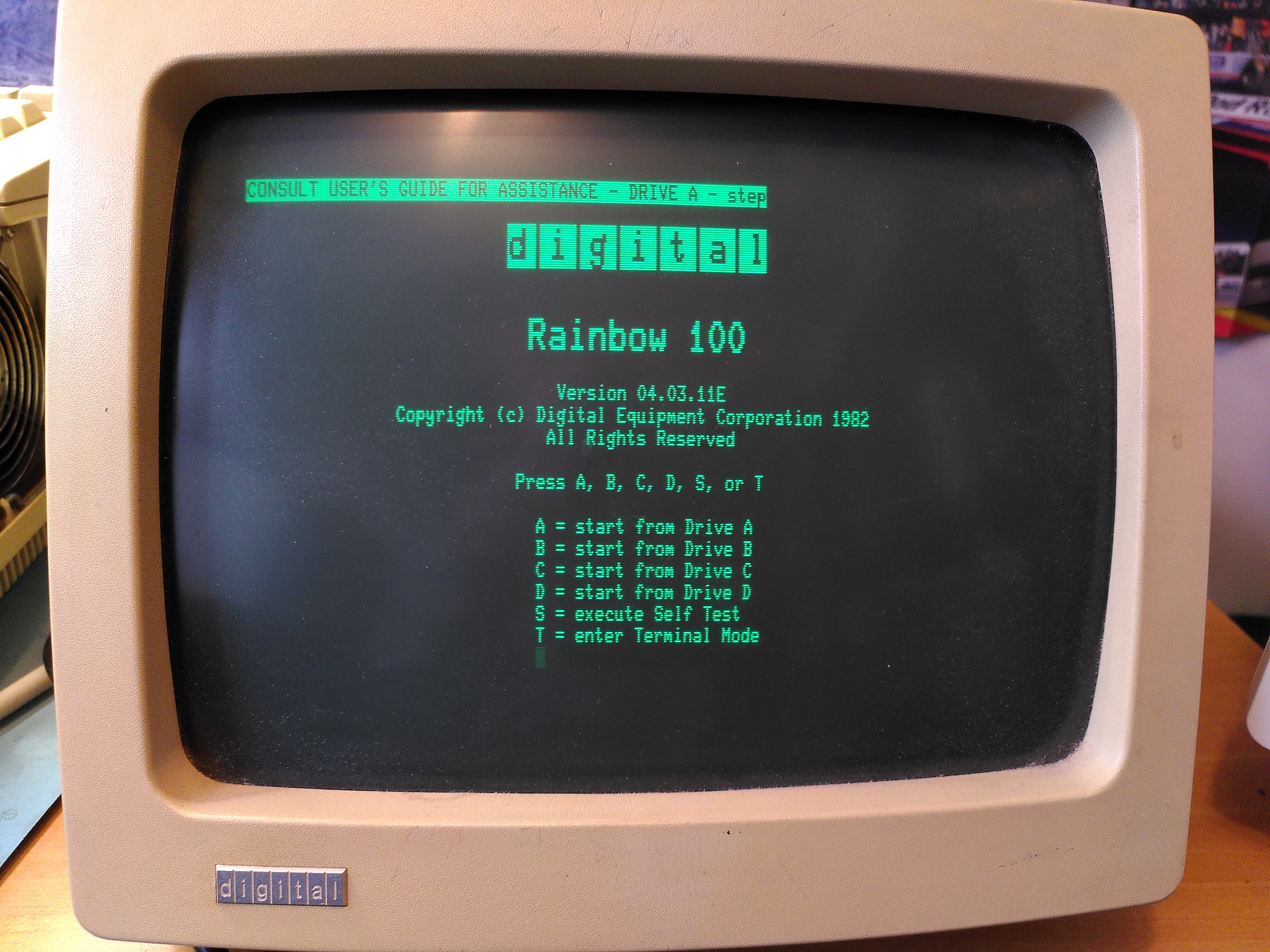
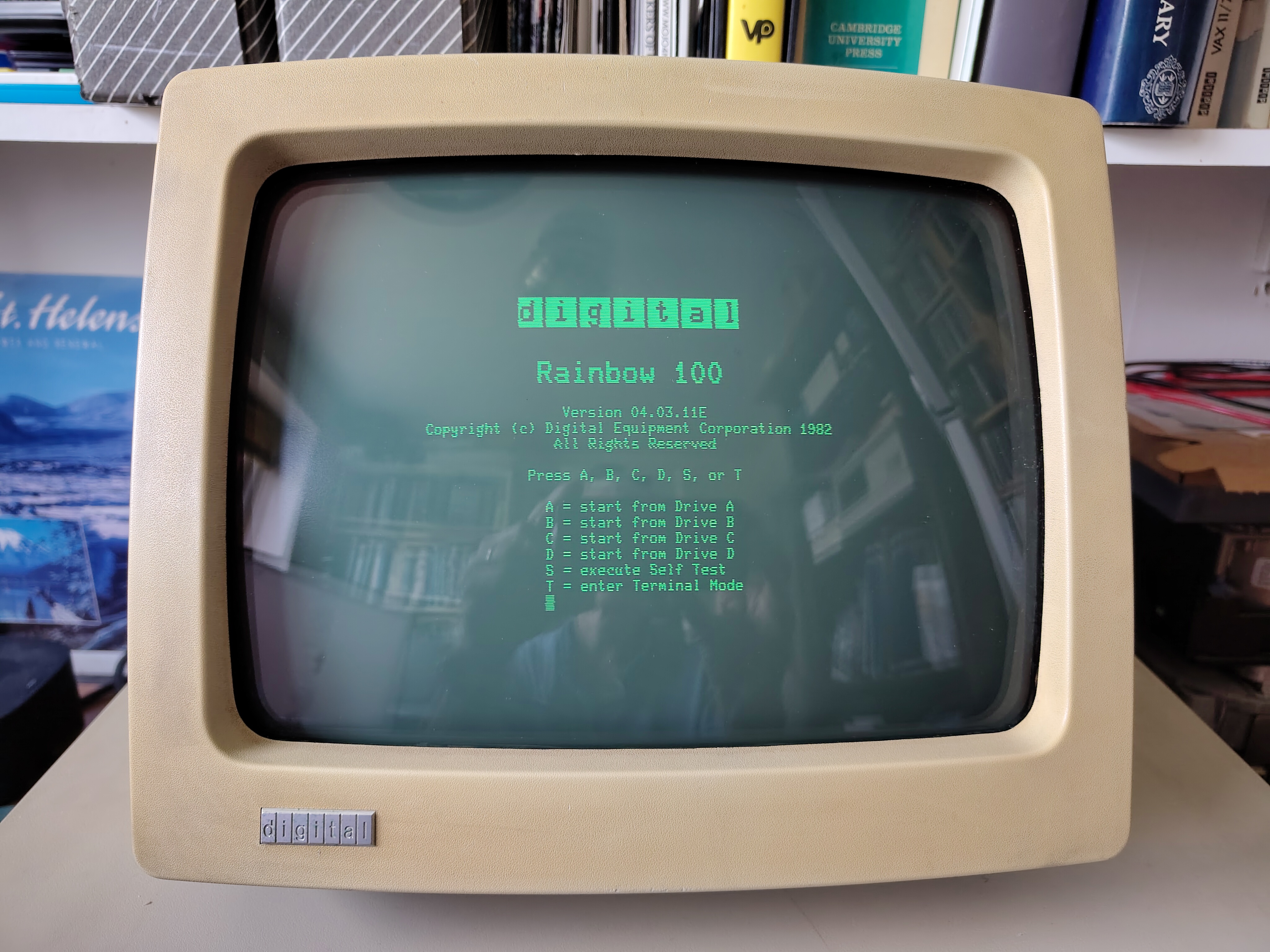
Replacing this fixed the screen display.
Rainbow 100A Working After Replacing the Faulty Line Buffer Chip
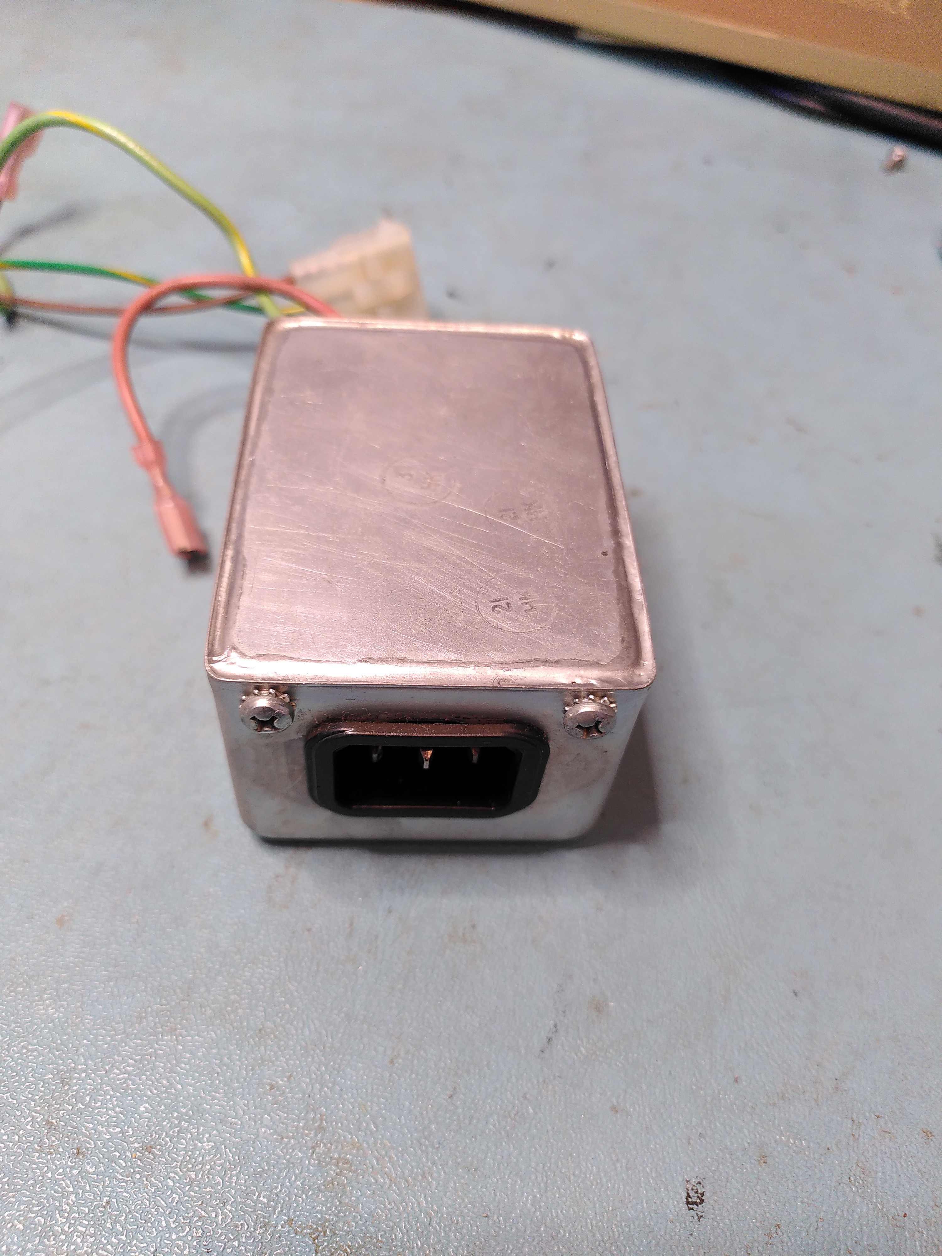
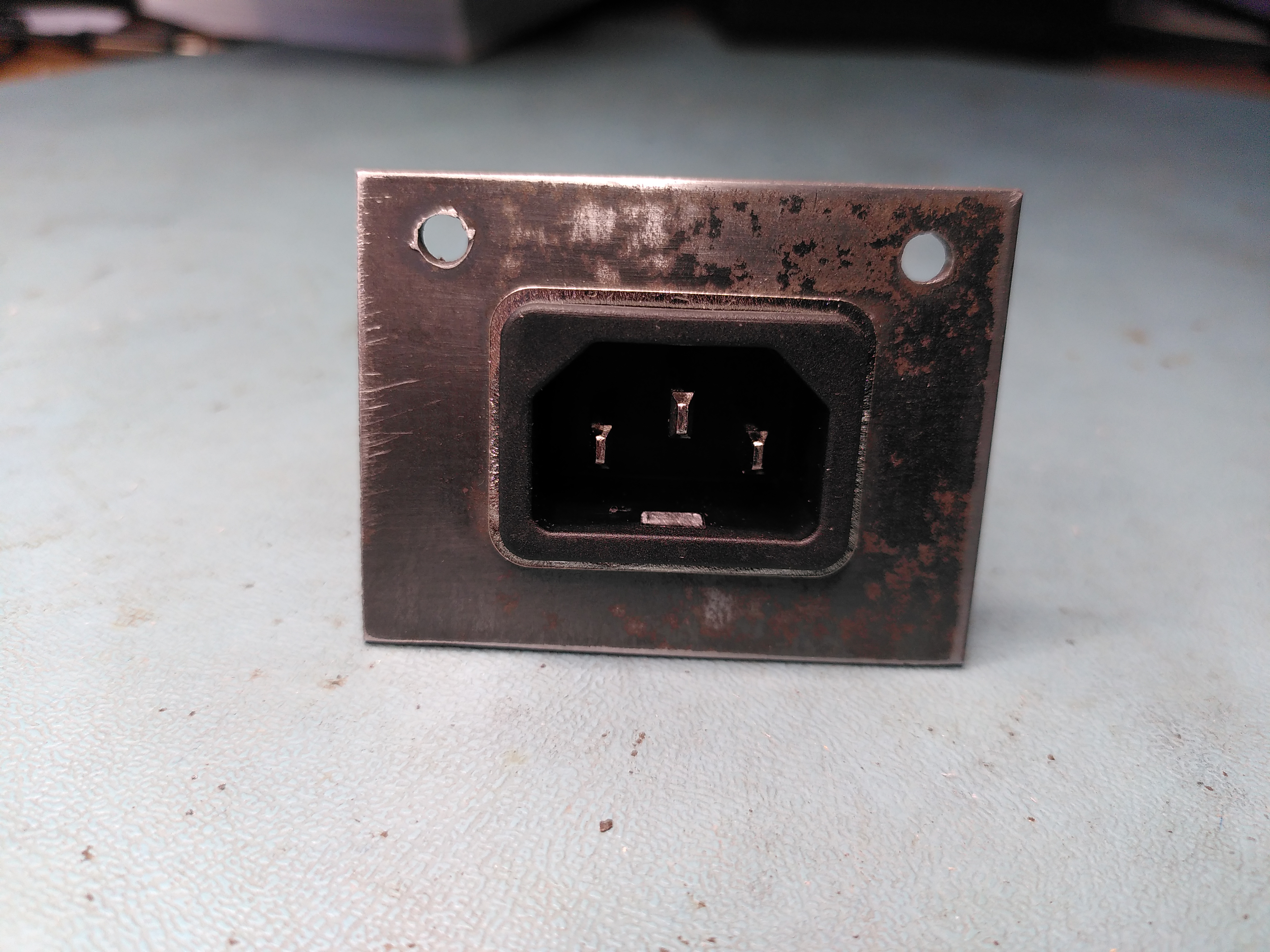
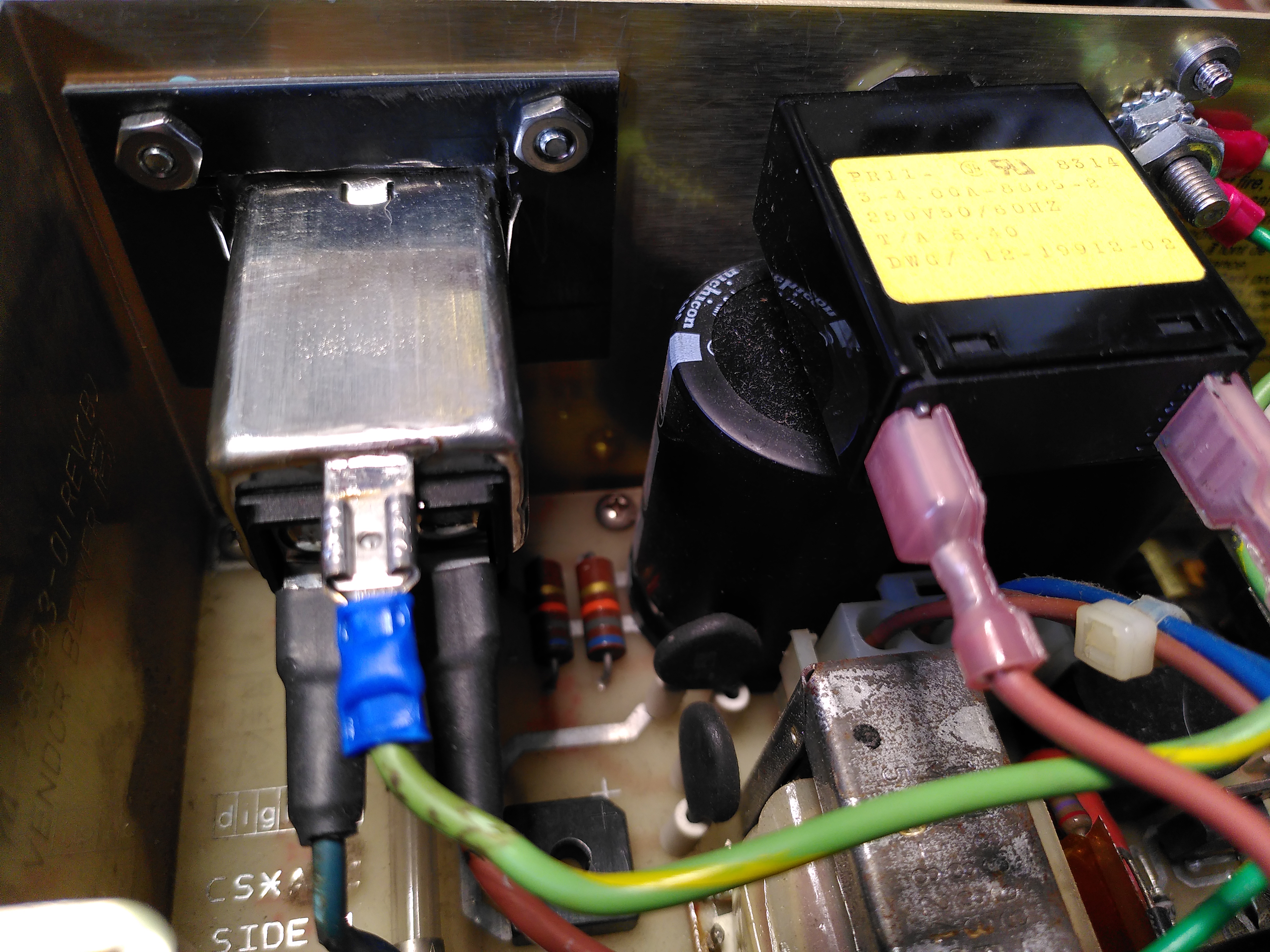
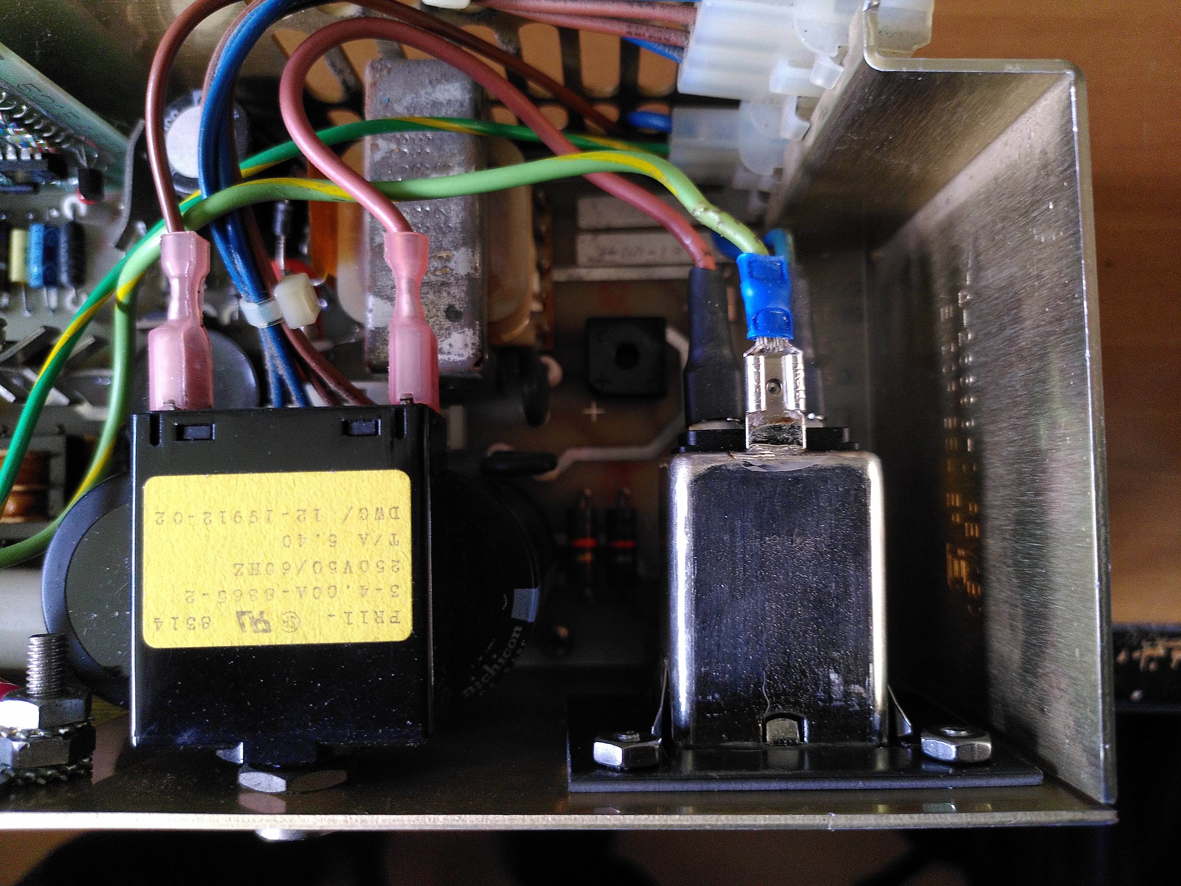
Unfortunately while diagnosing the line buffer chip fault the H7842A power supply stopped working. There was a pop when I plugged in the power cable, before the power supply was even switched on. Checking the power entry module, a Corcom F2987A, it measured a short across the inputs. I have had this happen before with one of these units.
The mounting for the power entry module is non-standard so it isn’t possible to just buy a modern replacement. I could not remember what I replaced it with when this happened before. I was advised that it is possible to open the unit and repair it, or just remove the components and not have a filter.
Soldered Cover on Corcom F2987A Power Entry Module
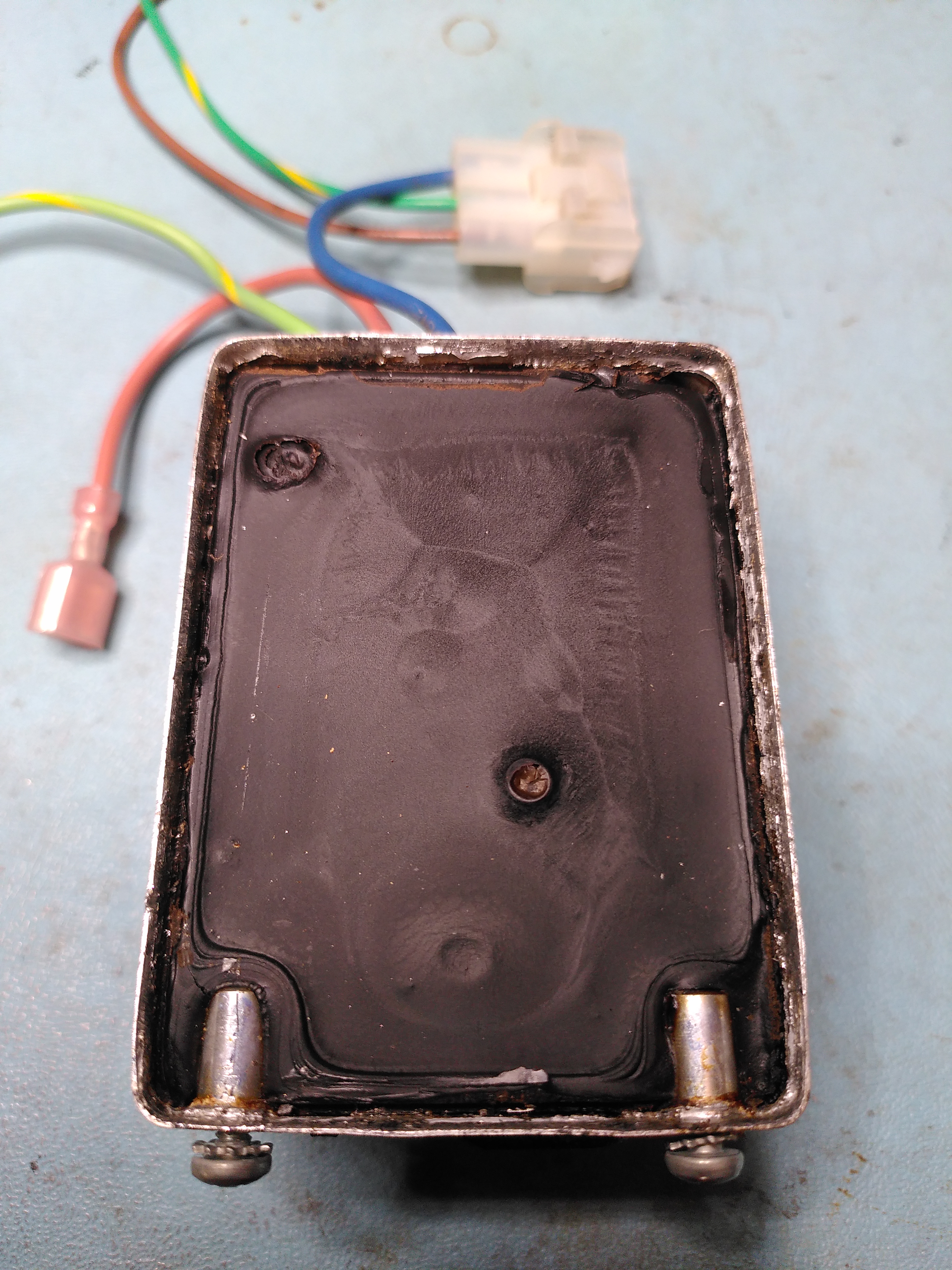
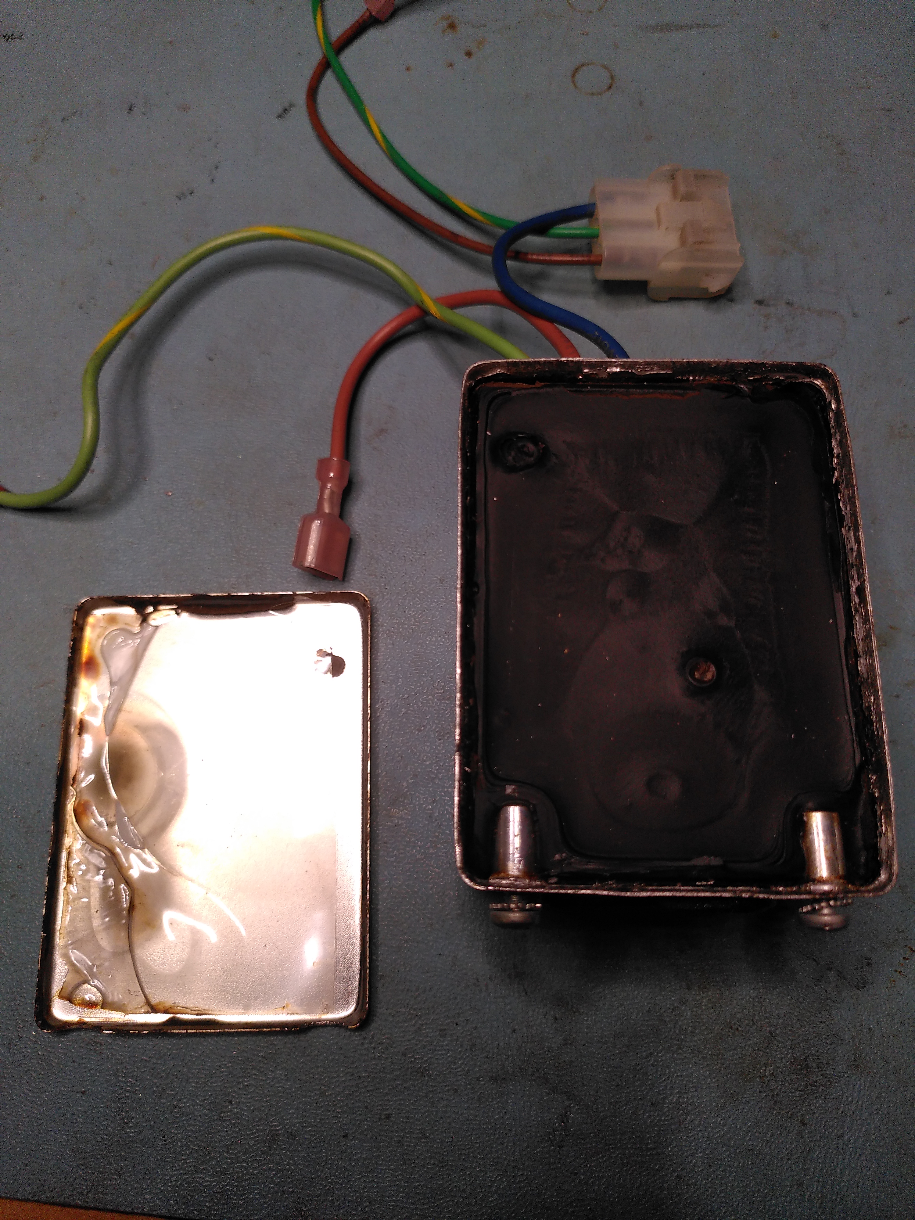
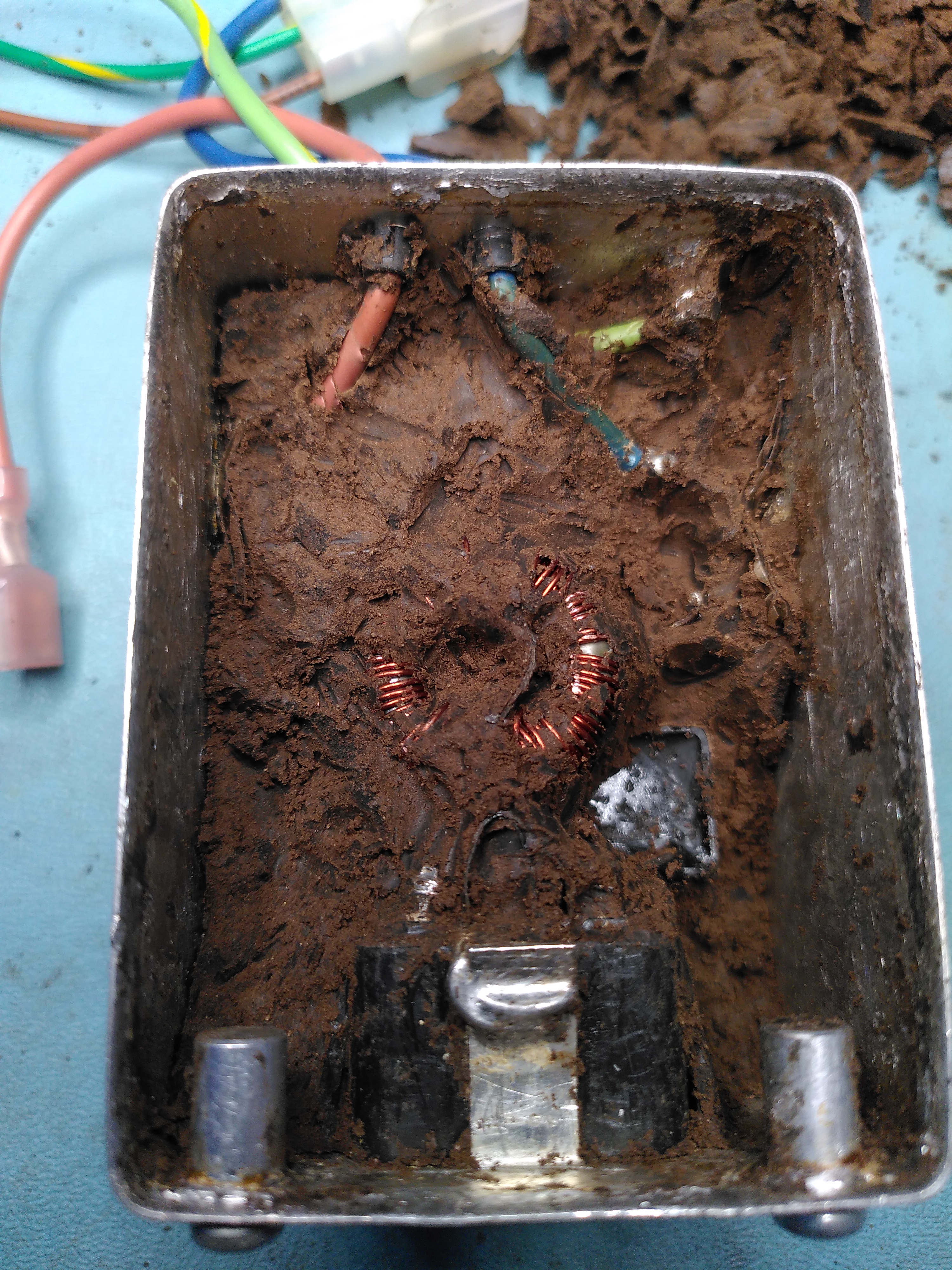
I elected to try opening it. The cover is soldered on though and being all metal it was really difficult to get enough heat to the solder to be able to open it. Eventually I managed to open it to be greeted by a huge blob of silicone.
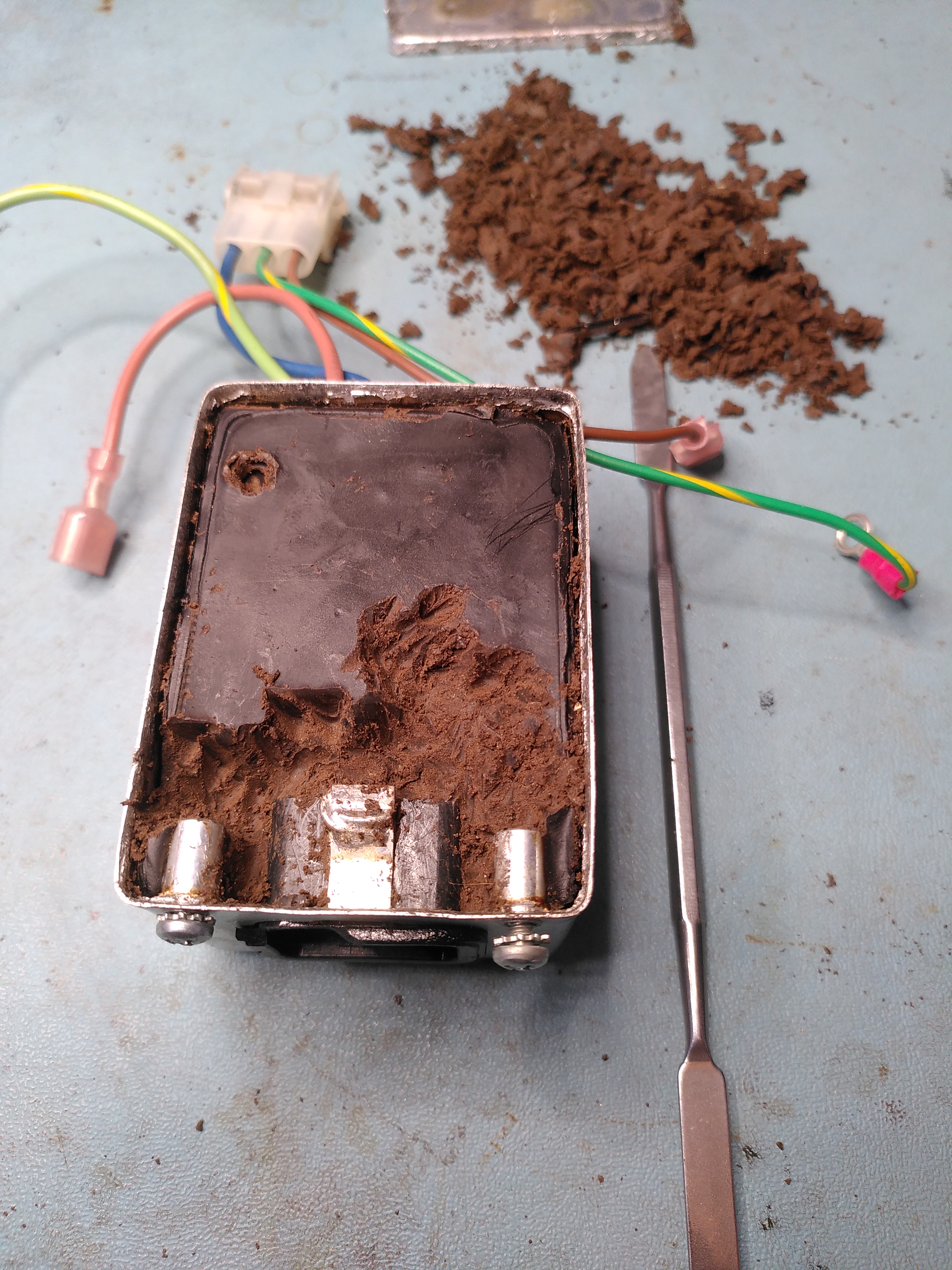
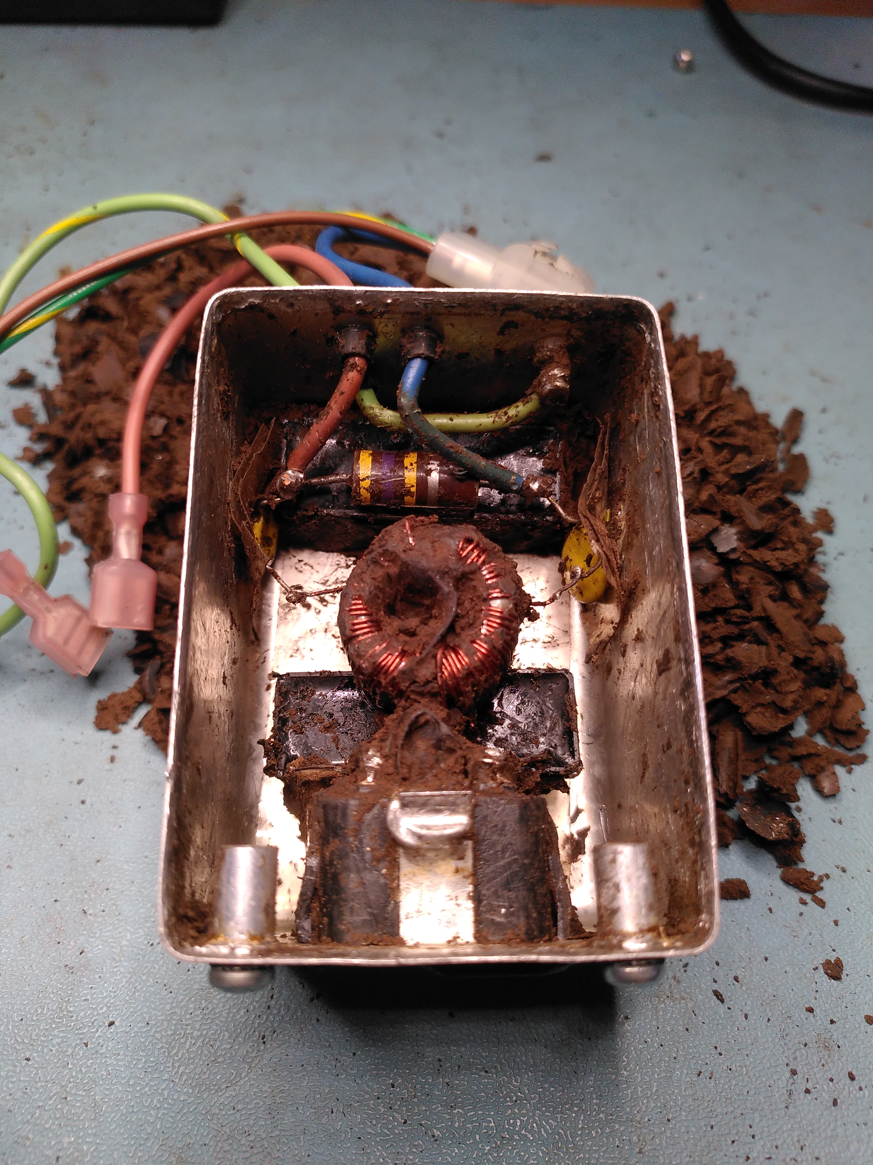
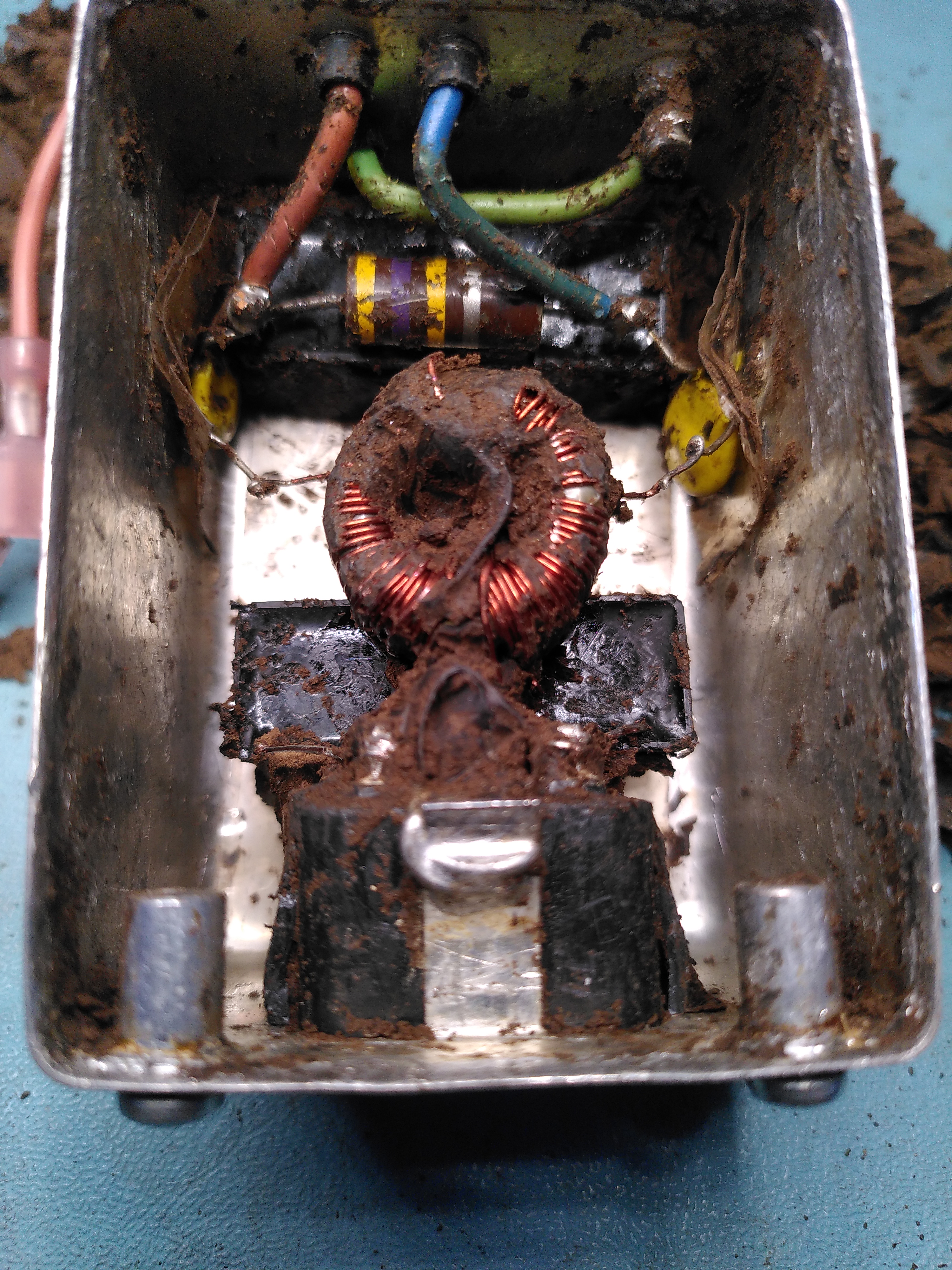
It was quite a job to excavate the components and I think I damaged the inductor in the process because one of the coils tested open circuit. I also managed to crack some of the edges on the actual inlet.
Excavating the Components in the Corcom F2987A Excavating the Components in the Corcom F2987A Excavating the Components in the Corcom F2987A Excavating the Components in the Corcom F2987A Excavating the Components in the Corcom F2987A
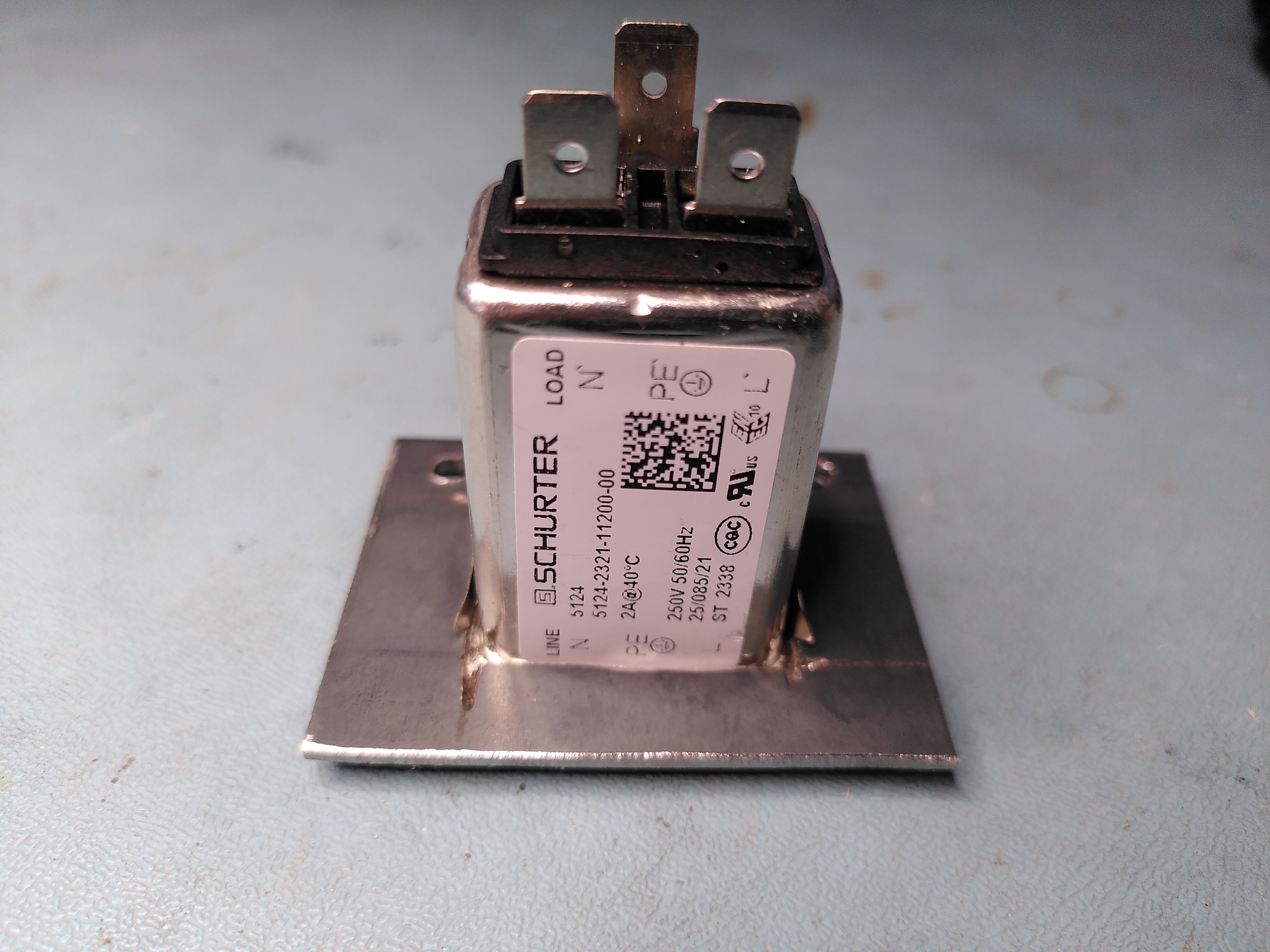
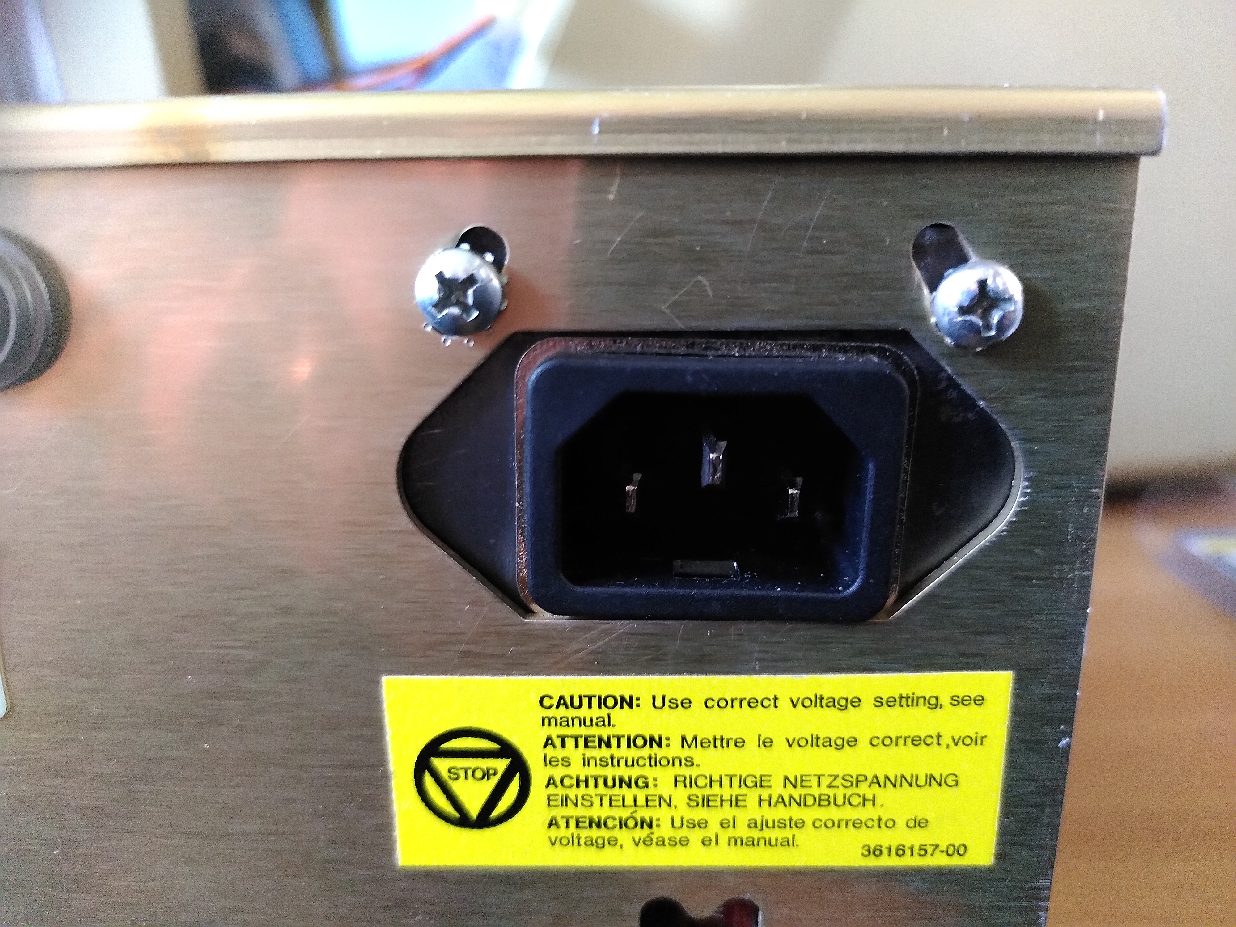
Given the damage I decided to use a modern power entry module. However I could not find any that would fit the hole in the enclosure of the original Corcom, so I got some 2mm steel and made a mounting plate in which I mounted a modern Schurter 5121 snap-in power entry module.
Schurter Power Entry Module in Mounting PlateSchurter Power Entry Module in Mounting PlateSchurter Power Entry Module Mounted in the PSUSchurter Power Entry Module Mounted in the PSUSchurter Power Entry Module Mounted in the PSUSchurter Power Entry Module Mounted in the PSUSchurter Power Entry Module Mounted in the PSU
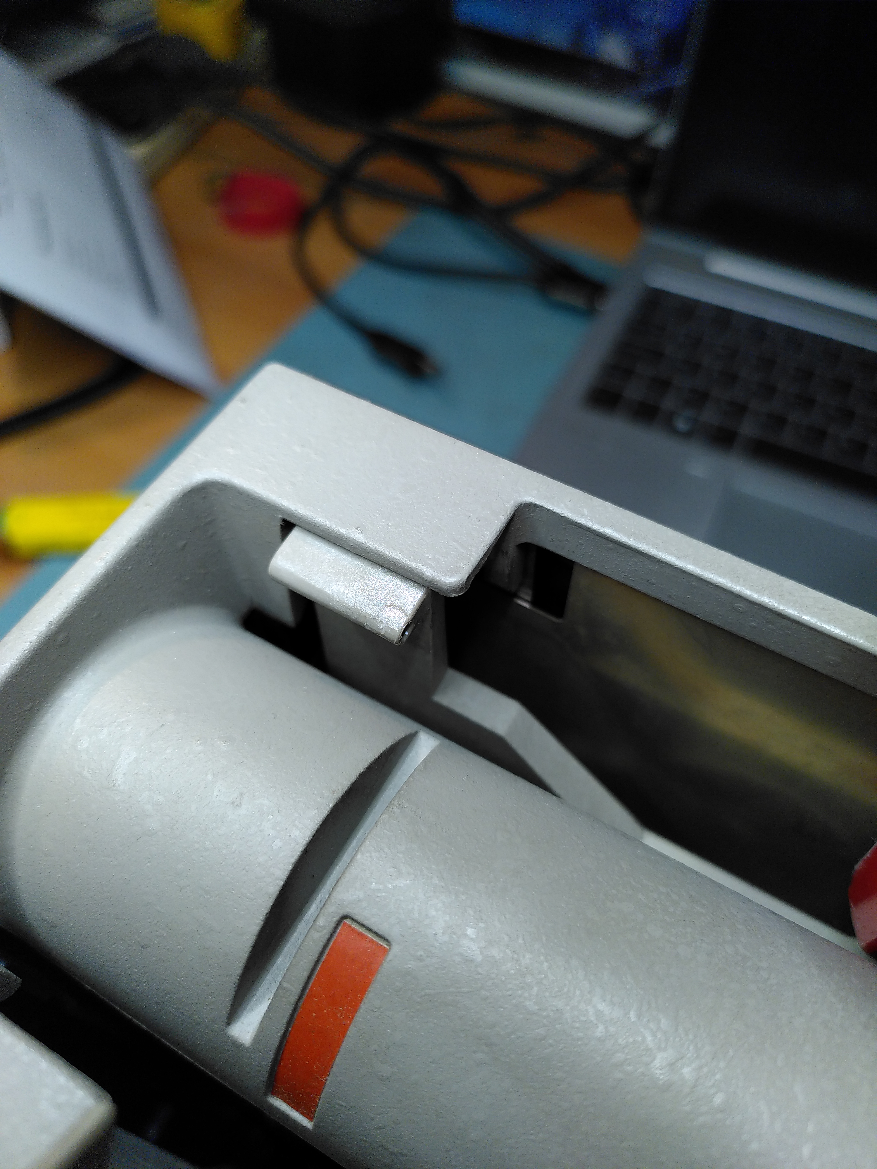
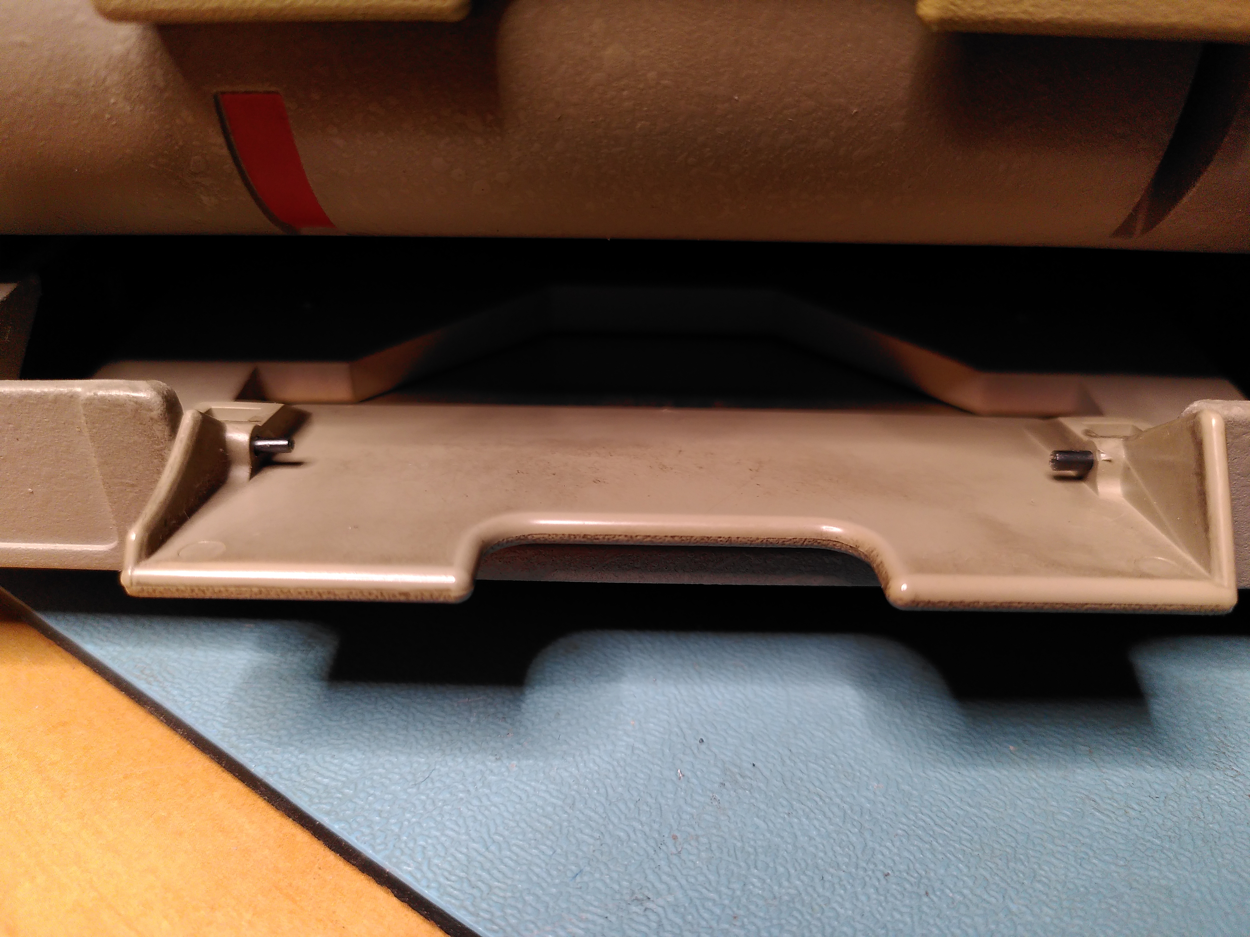
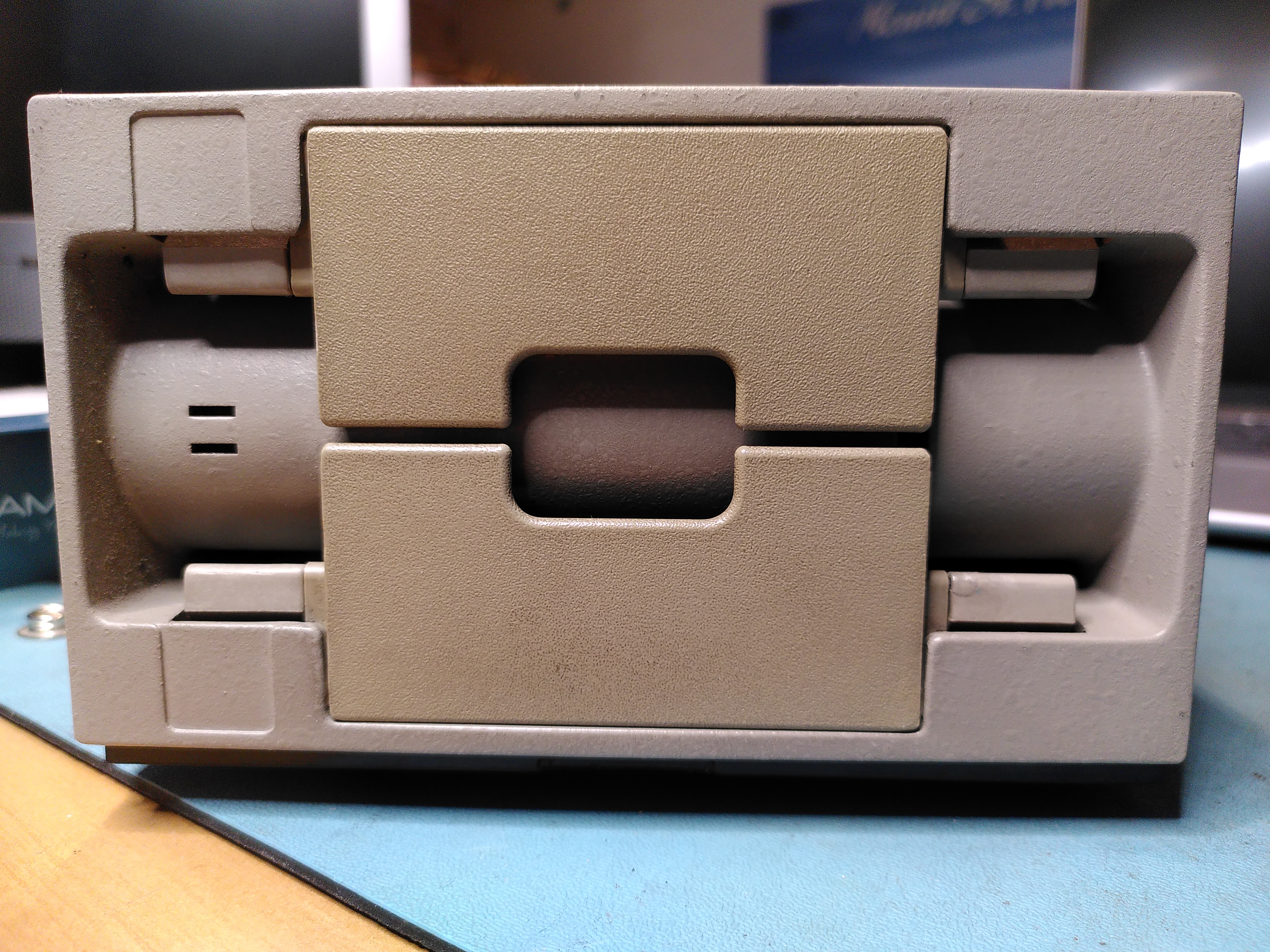
RX50 Floppy Disk Drive Door
The RX50 floppy disk drive had one of its doors adrift. The pins holding it in have been lost and one of the mounting holds was a little damaged. I glued back the damaged plastic to repair the mounting hole using ProWeld.
I didn’t know where to get new mounting pins so I found something similar on eBay. Although not being polished they are stiffer. The new pins were slightly too big, but thankfully their design allowed me to reduce the diameter and I was able to fit them.
The door is now back on, although a little stiffer.
RX50 Door Mount After GluingRX50 Door With Replacement PinsRepaired RX50 Door
RX50 Not Reading Disks
During my work on trying to restore this machine I also found that the RX50 would not read any disks. By comparing with a known good RX50 it didn’t take long to realise that it was not spinning the disks. On startup it runs both the head stepper motor and the spindle motor. But the spindle was not rotating.
On closer inspection I found that it was trying to turn the spindle but it just twitched slightly. I found that the spindle was quite hard to turn by hand, certainly compared to the known good RX50. I started to take it apart a bit and after the cone lift covers came off the spindle moved more freely.
I did a few checks and this seemed to be the problem. Reassembling the drive fixed the issue. I suspect that one of the cone lift covers was not correctly aligned. Possibly as a result of whatever had damaged the door, or possibly as a result of my attempts to fix the door. Whatever the cause the RX50 now works.
I also managed to damage the cable slightly because it is close to a sharp corner on the PSU and it is easy to crush the wires. The damage seems intermittent, but clearly the cable is not in good condition.
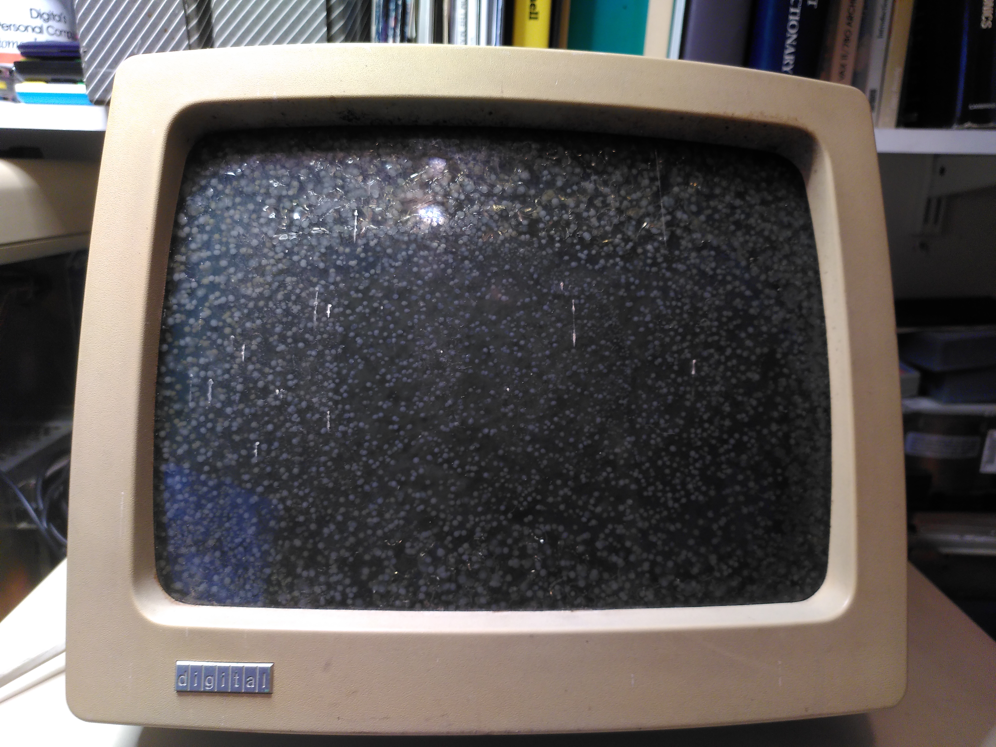
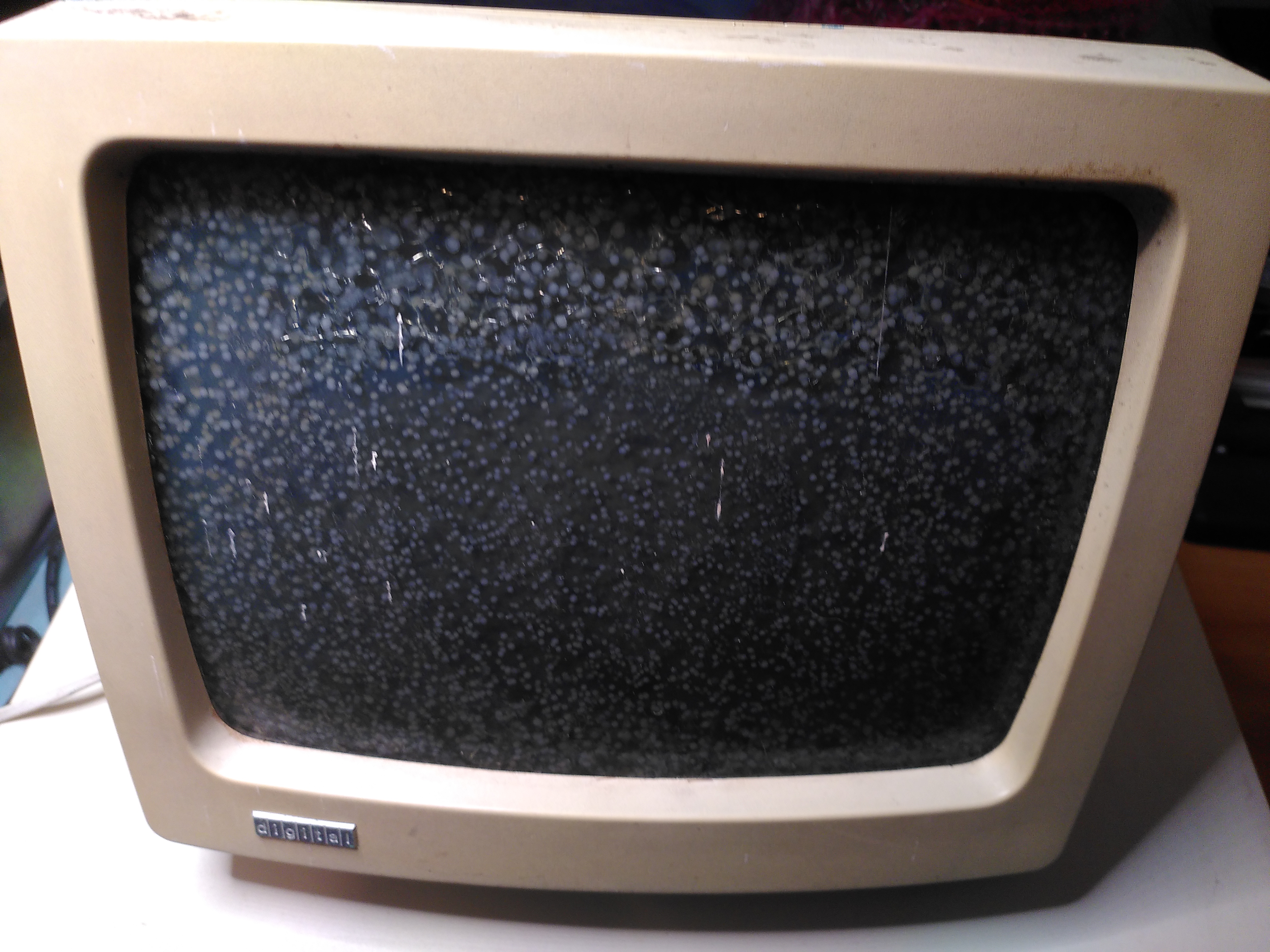
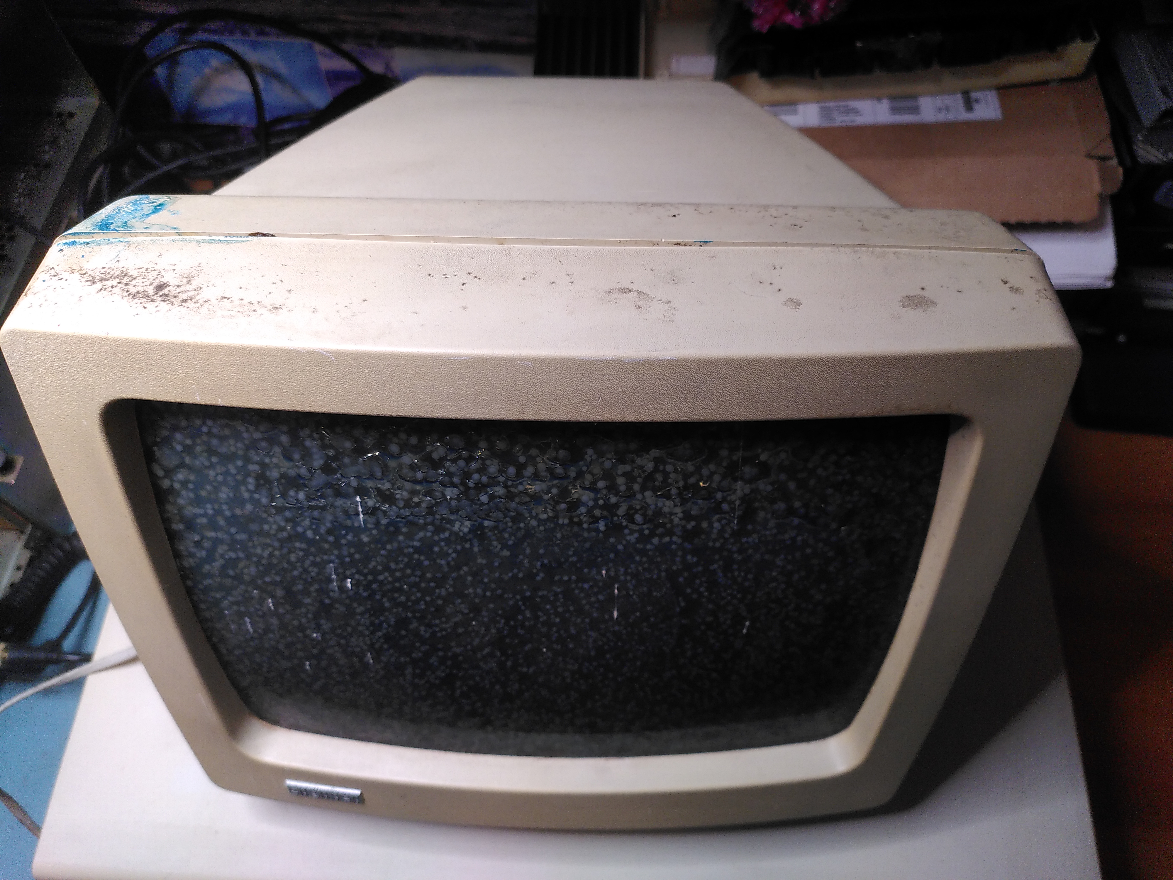
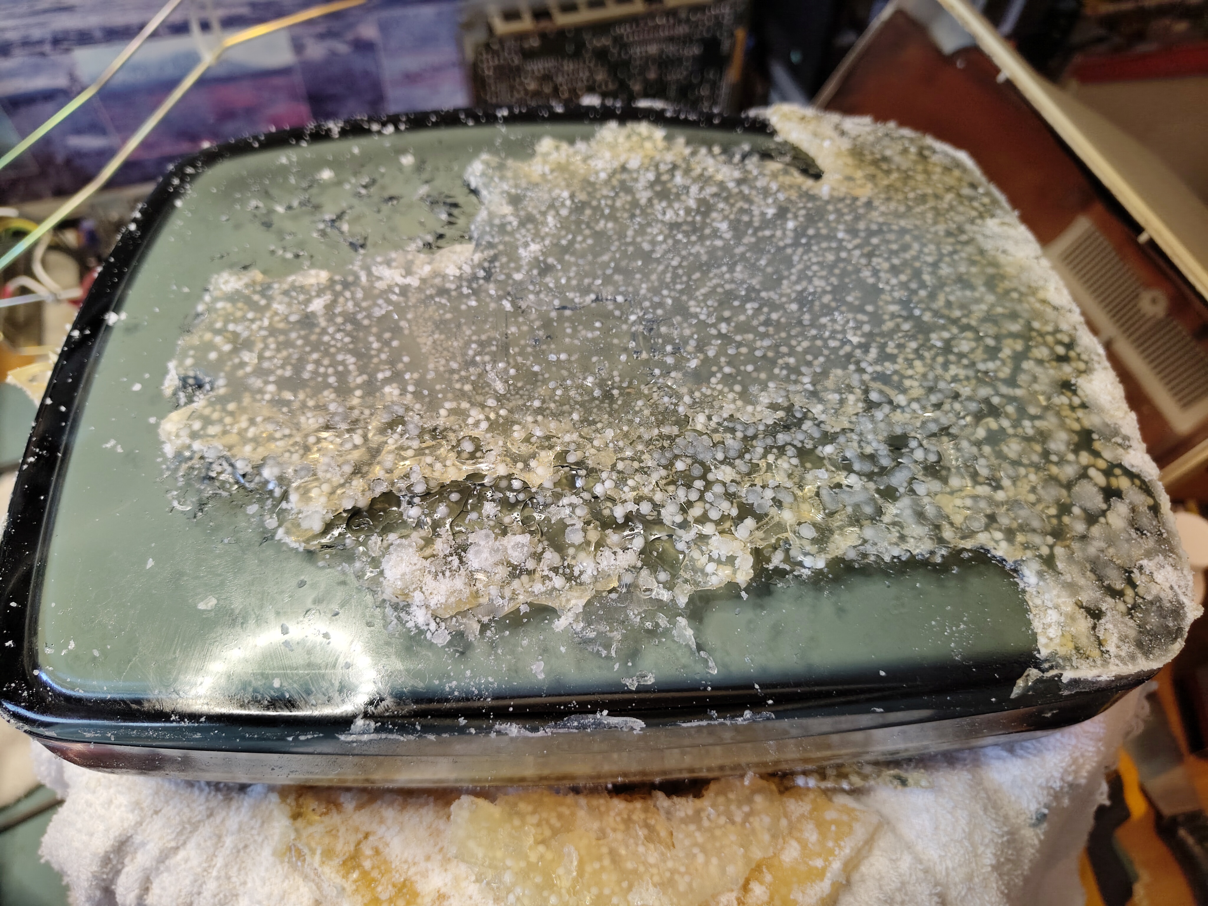
Screen Cataracts
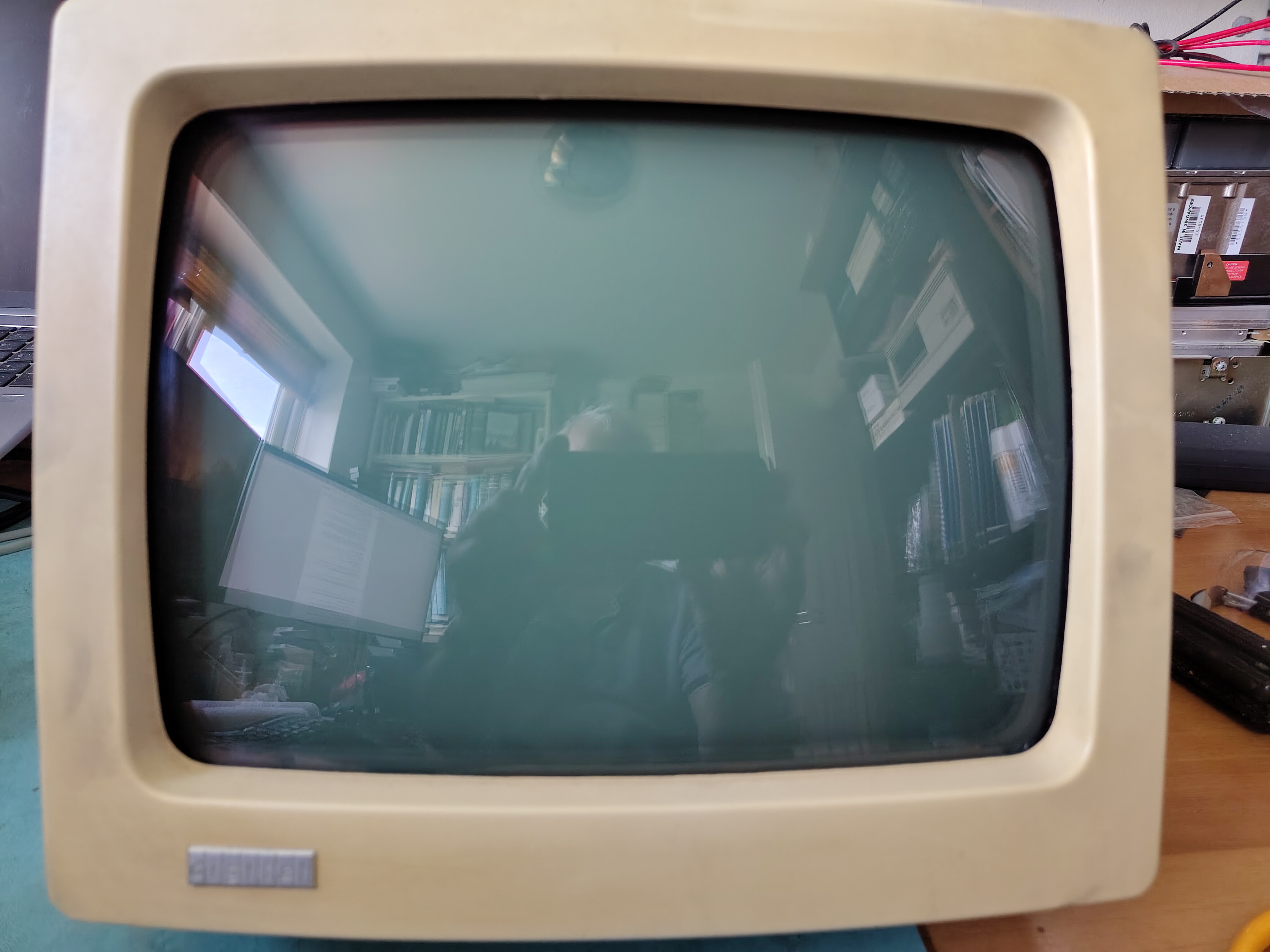
The VR201 had some pretty bad cataracts when I collected the machine, but it does appear to work.
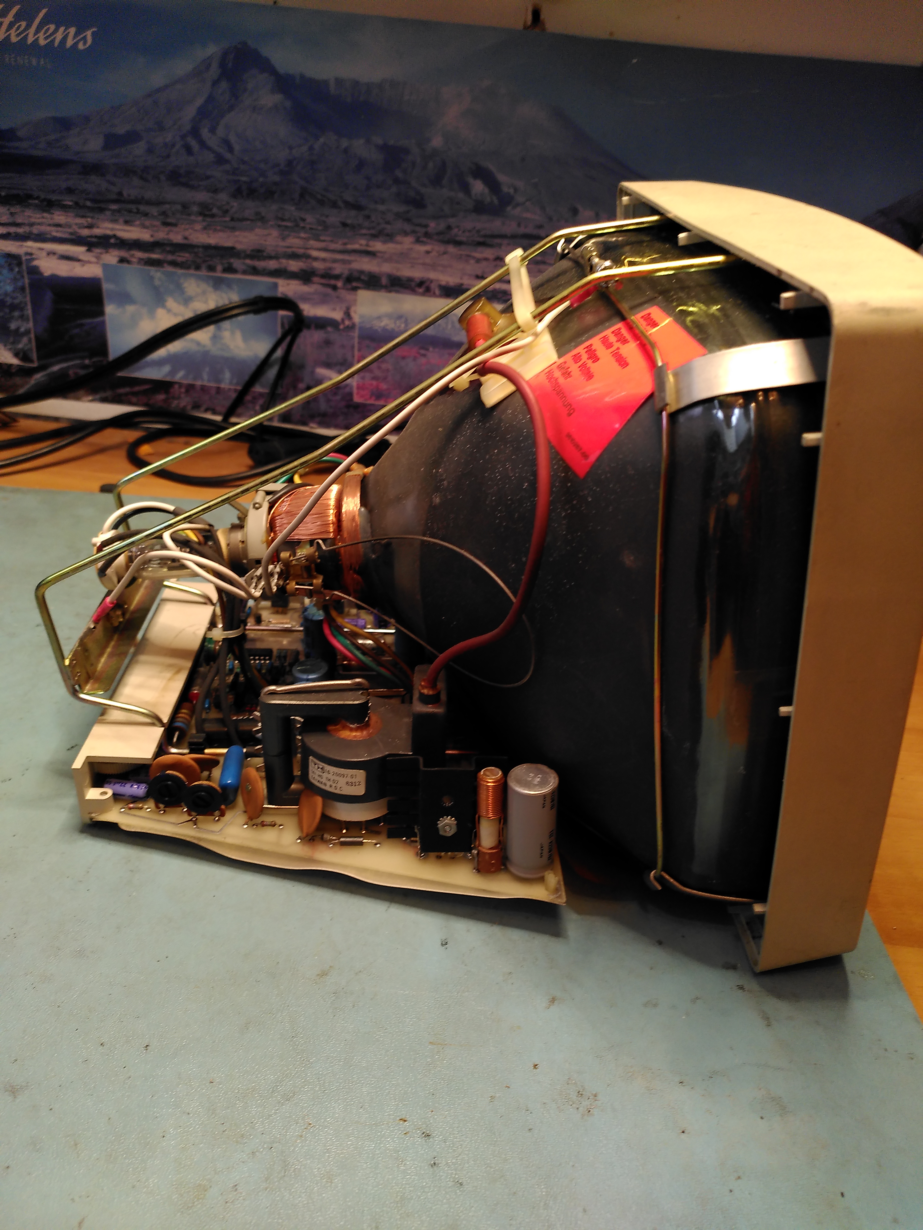
Fixing cataracts is not something I have done before. I followed this guidance from the VCF Forums and this too, in particular for dismantling the VR201. Removing the cover showed the interior to be very clean.
Interior of VR-201 Monitor
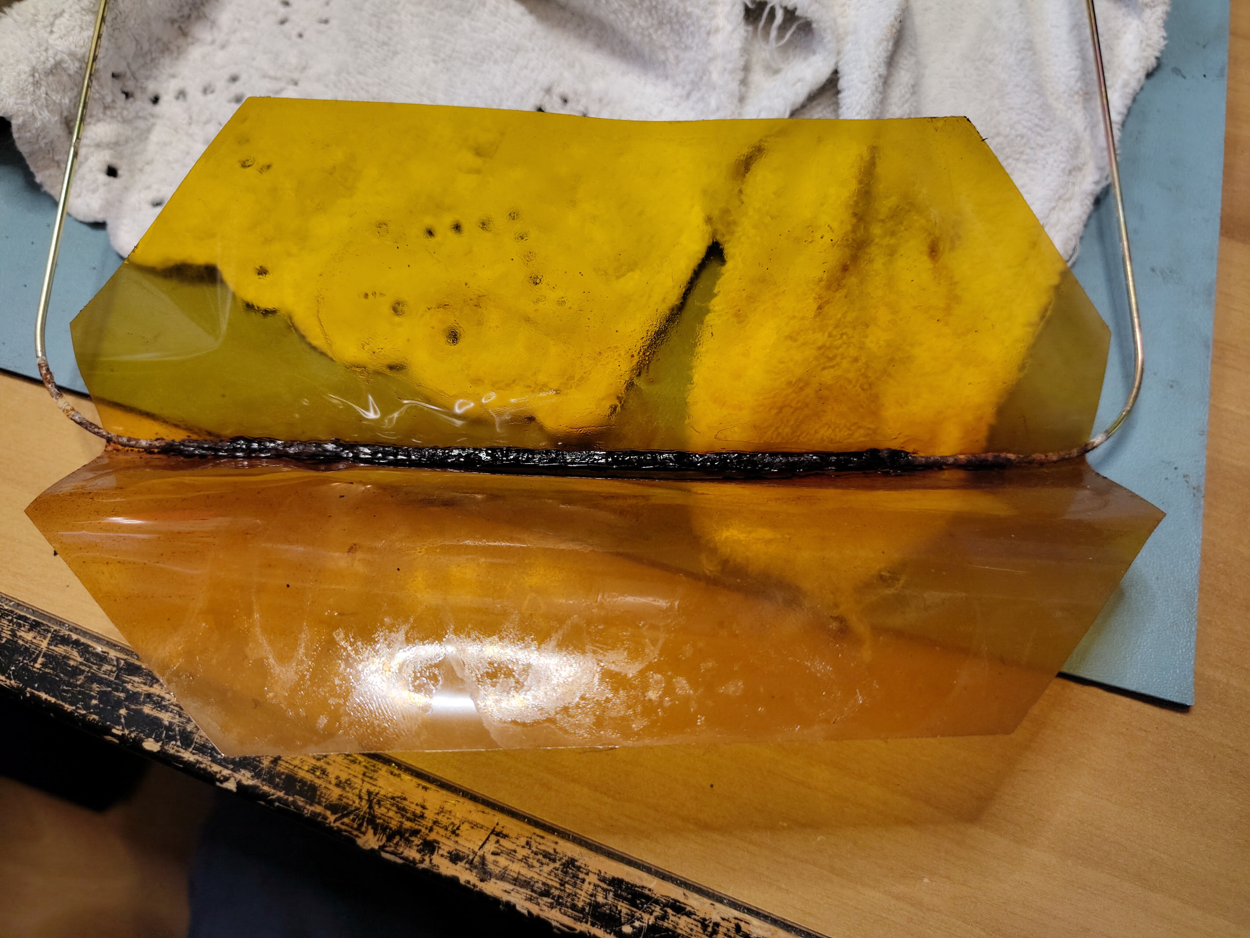
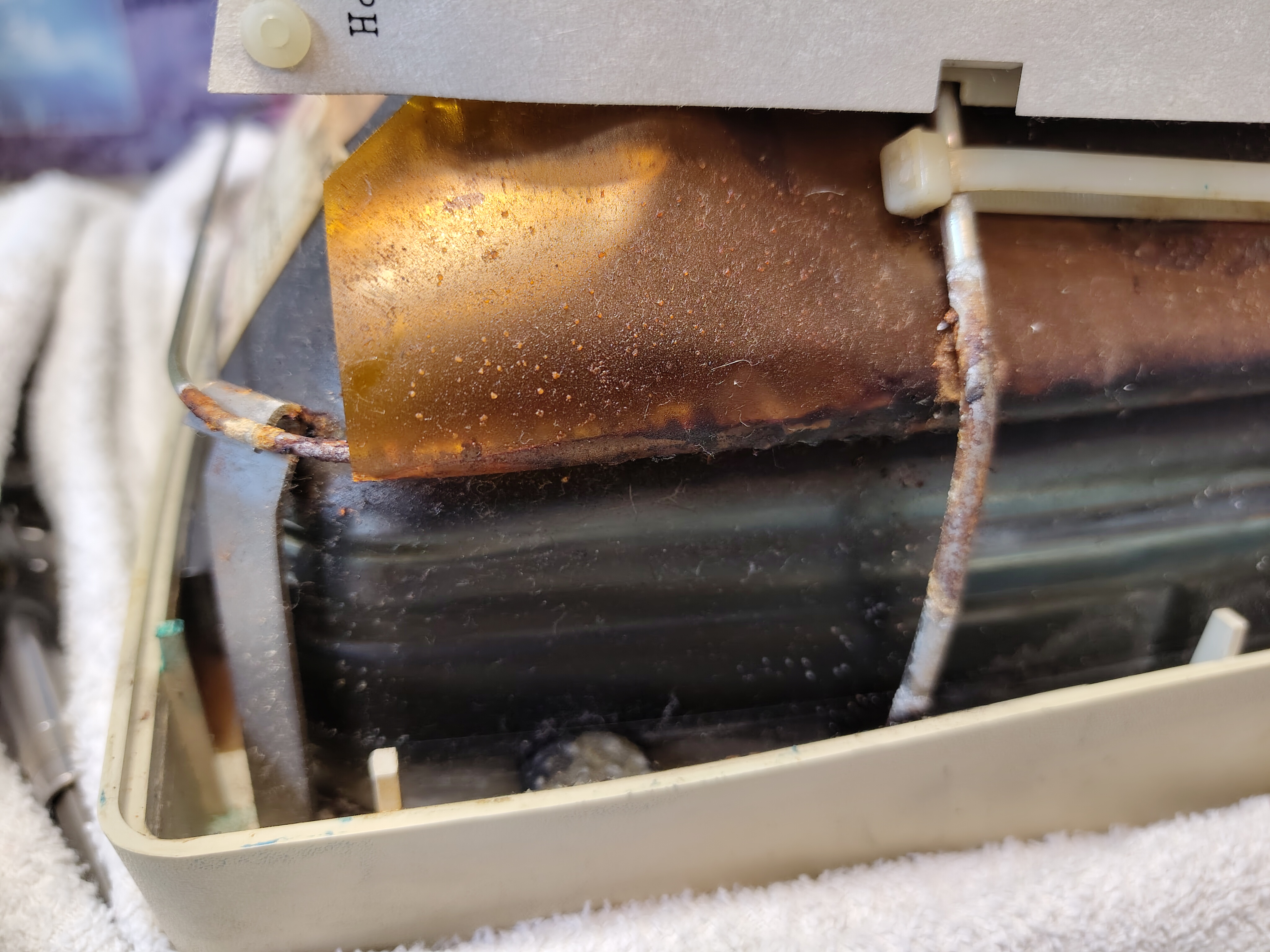
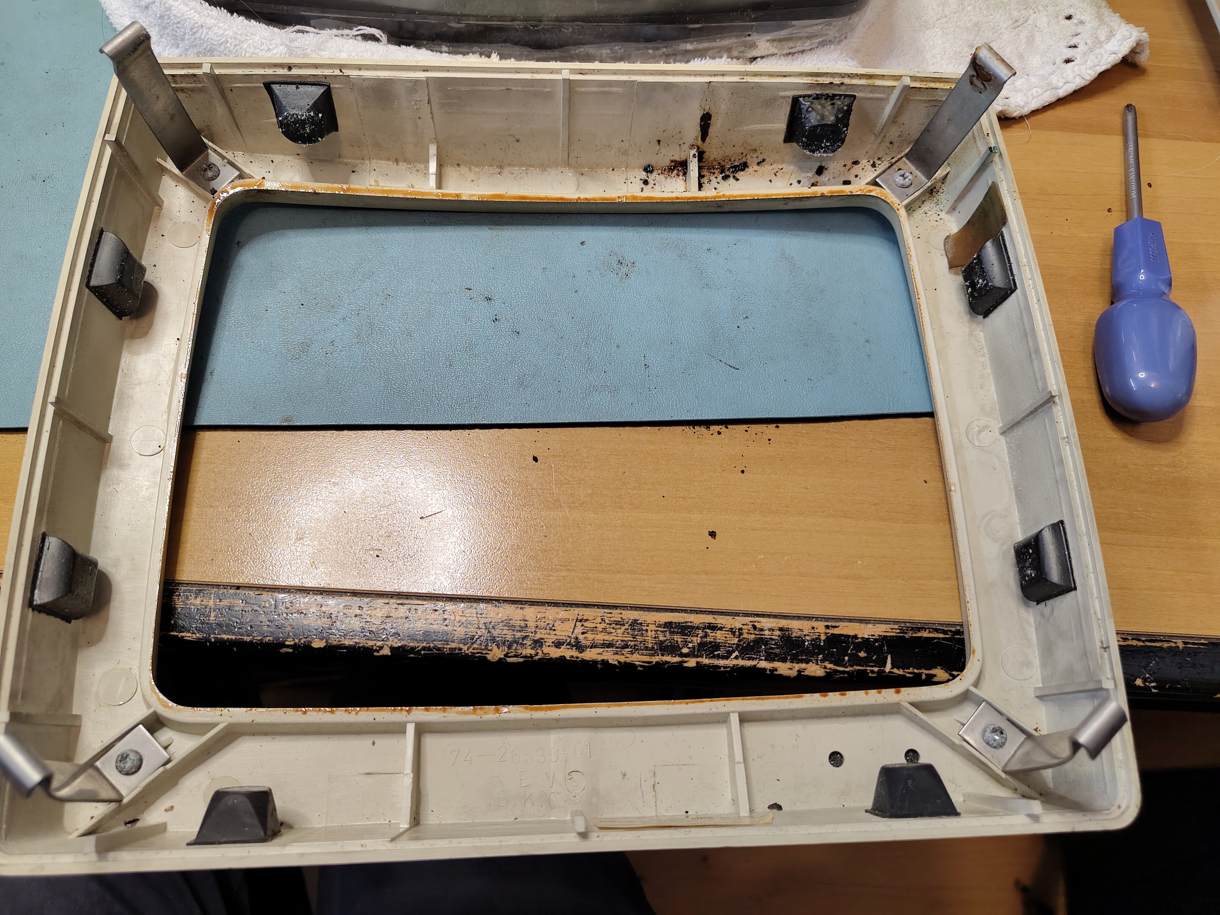
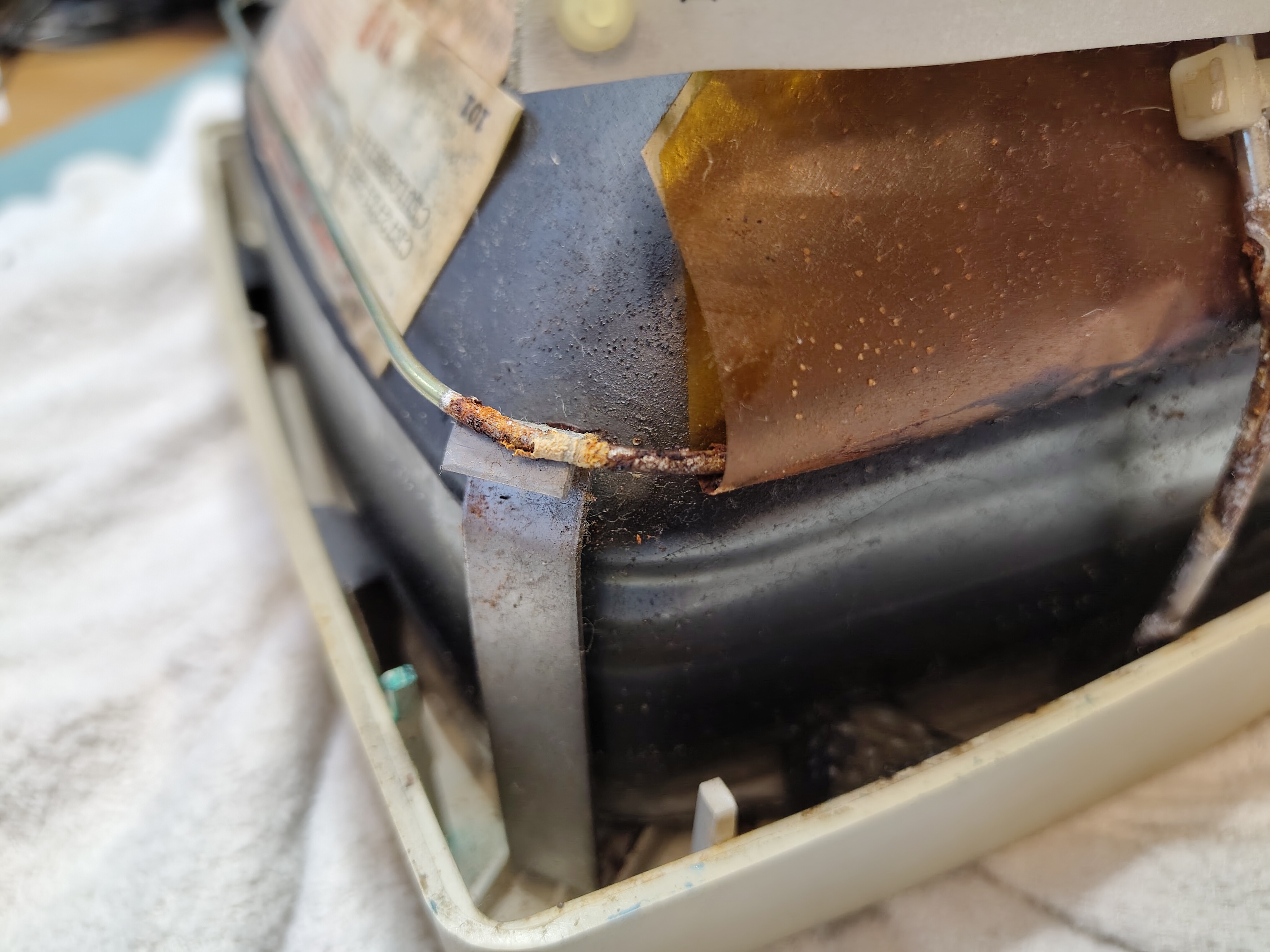
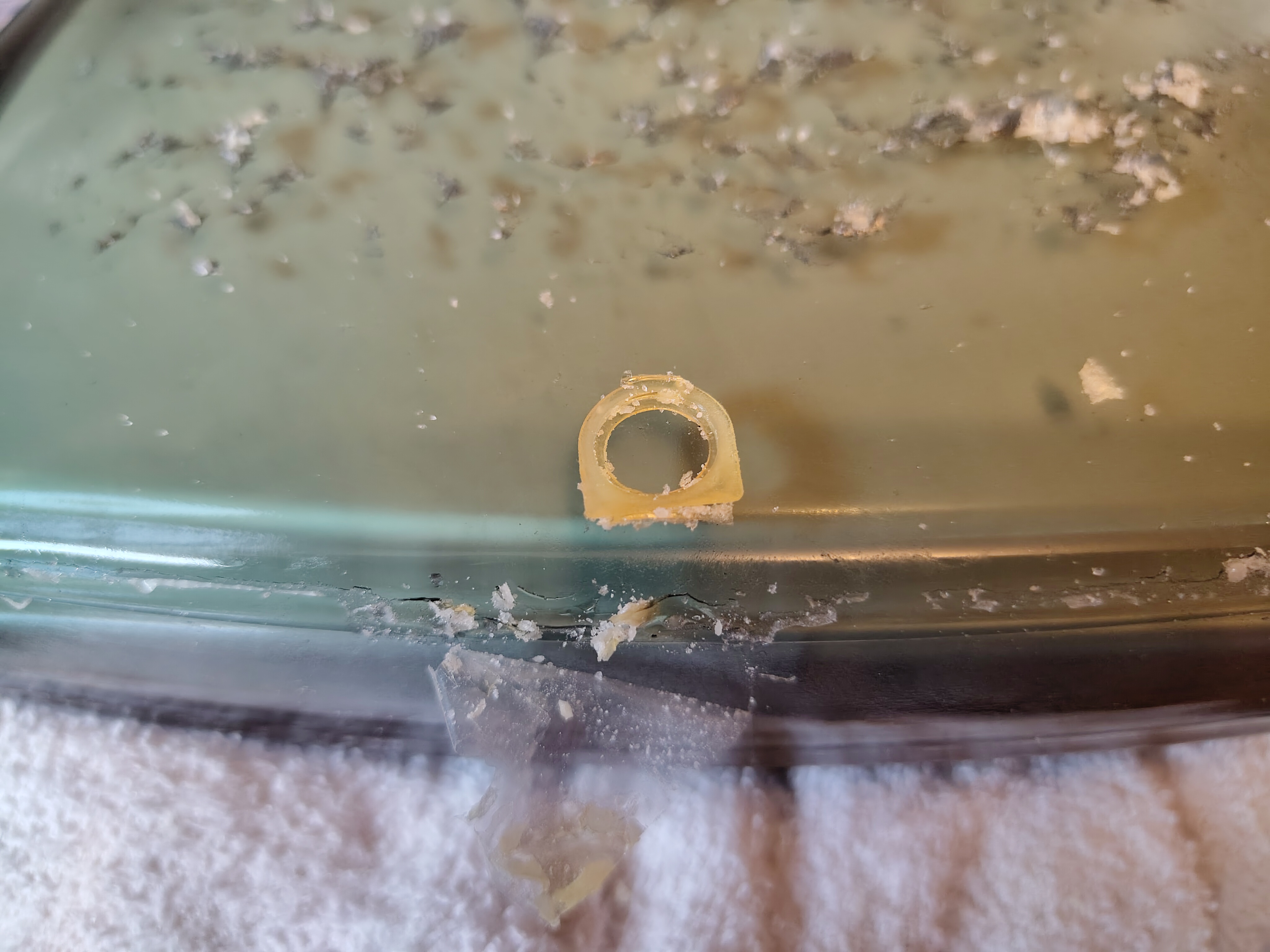
I made sure the anode cap was discharged first. Then I removed the brace that attaches the CRT to the bezel and the cables connecting to the tube. I found what looked like a rusty gunge in parts of the brace and what looked like a bit of mild corrosion. I am not sure what the gunge was, but VCF forum posts suggest it is PVA and corrosive, however, once I had removed it the corrosion didn’t seem to bad.
Rusty Gunge in the Acrylic SheetMild Corrosion of the FrameSome of the Rusty Gunge on the TubeThe Back of the Screen BezelMore Mild Corrosion of the Frame
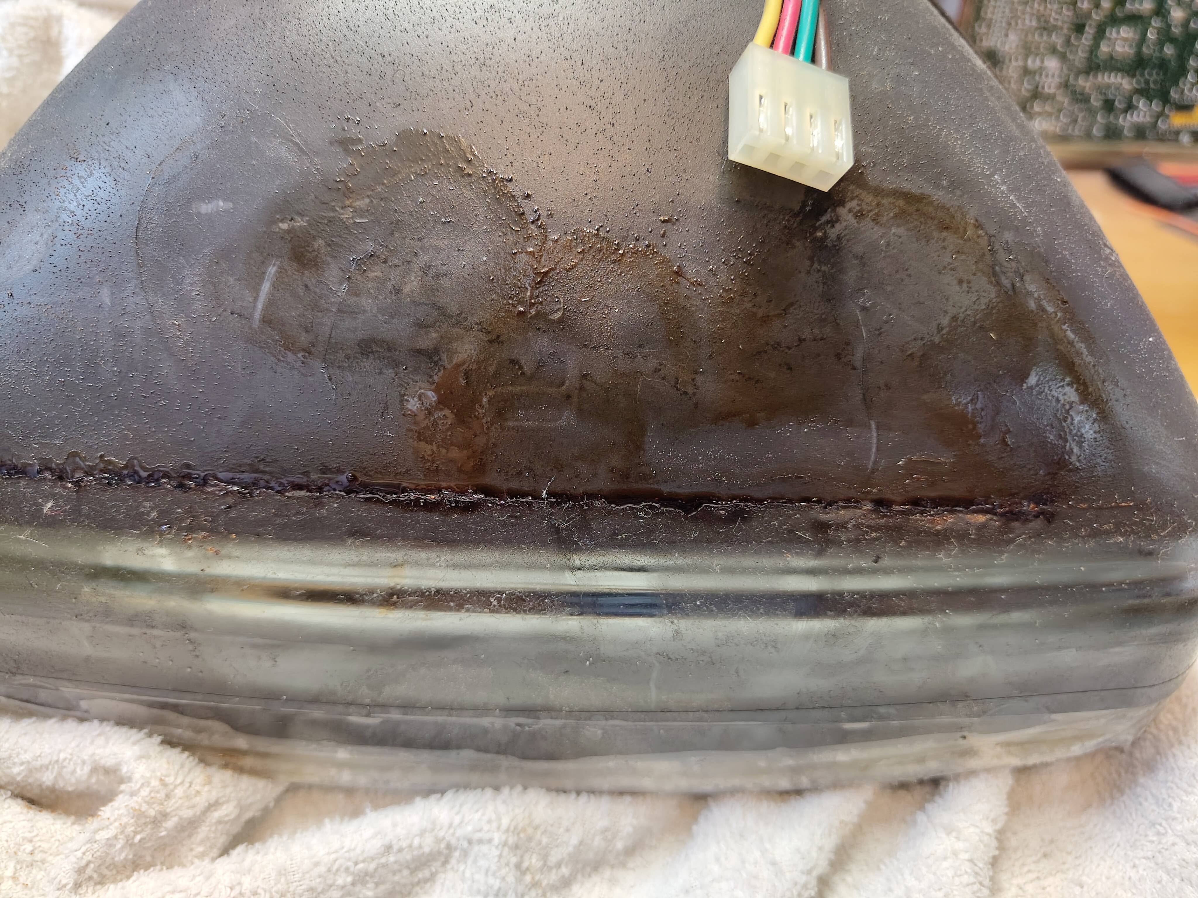
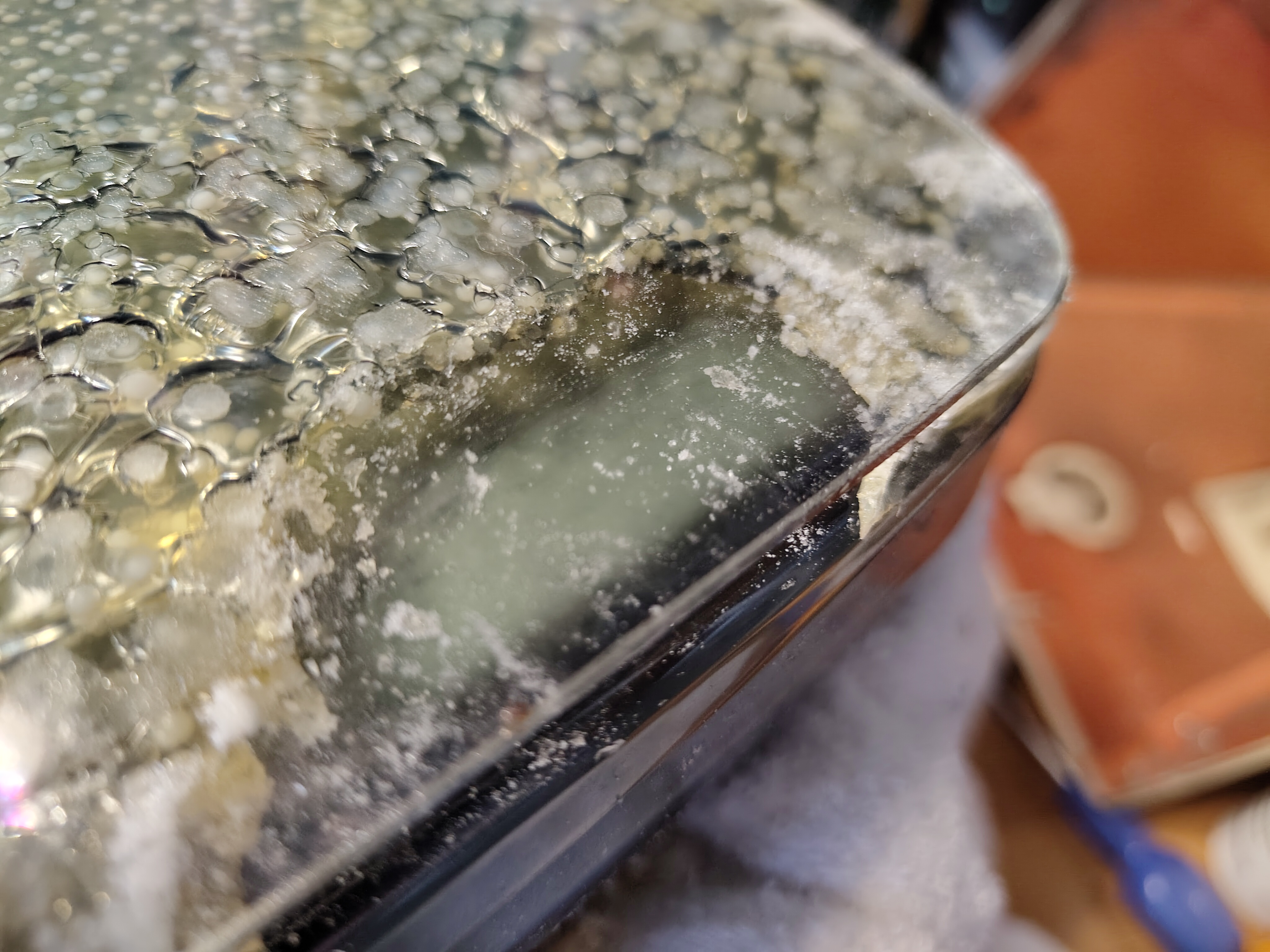
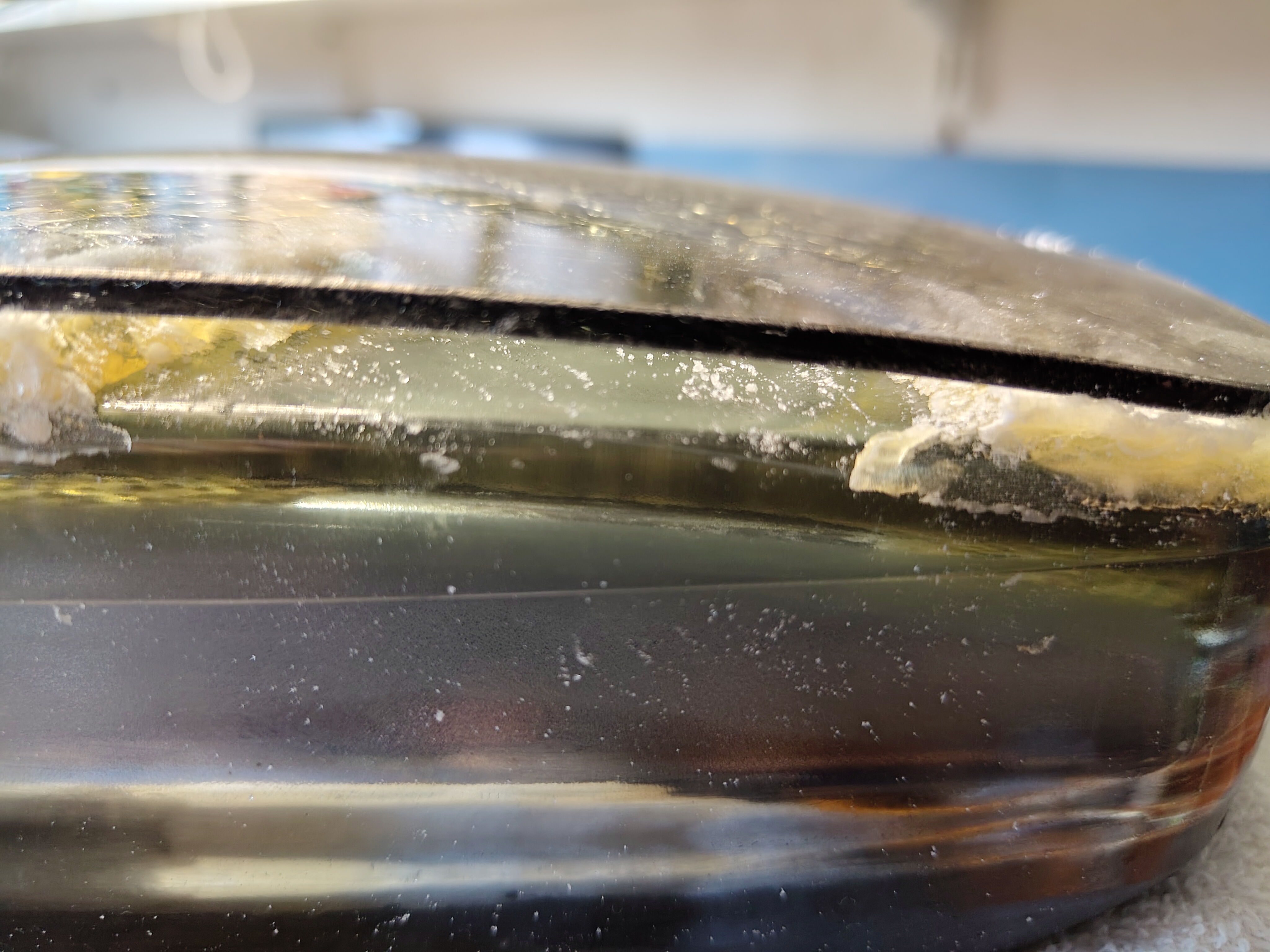
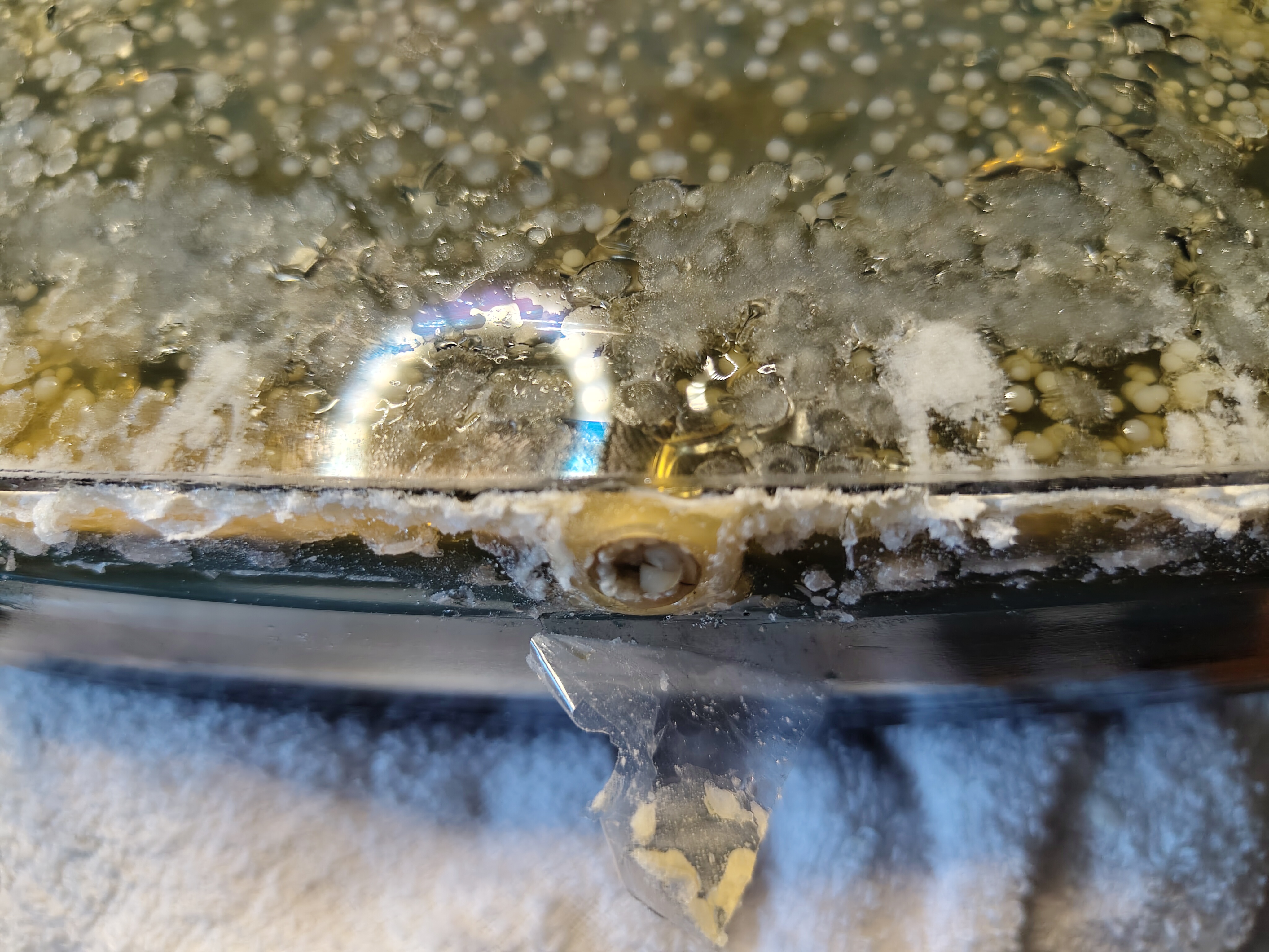
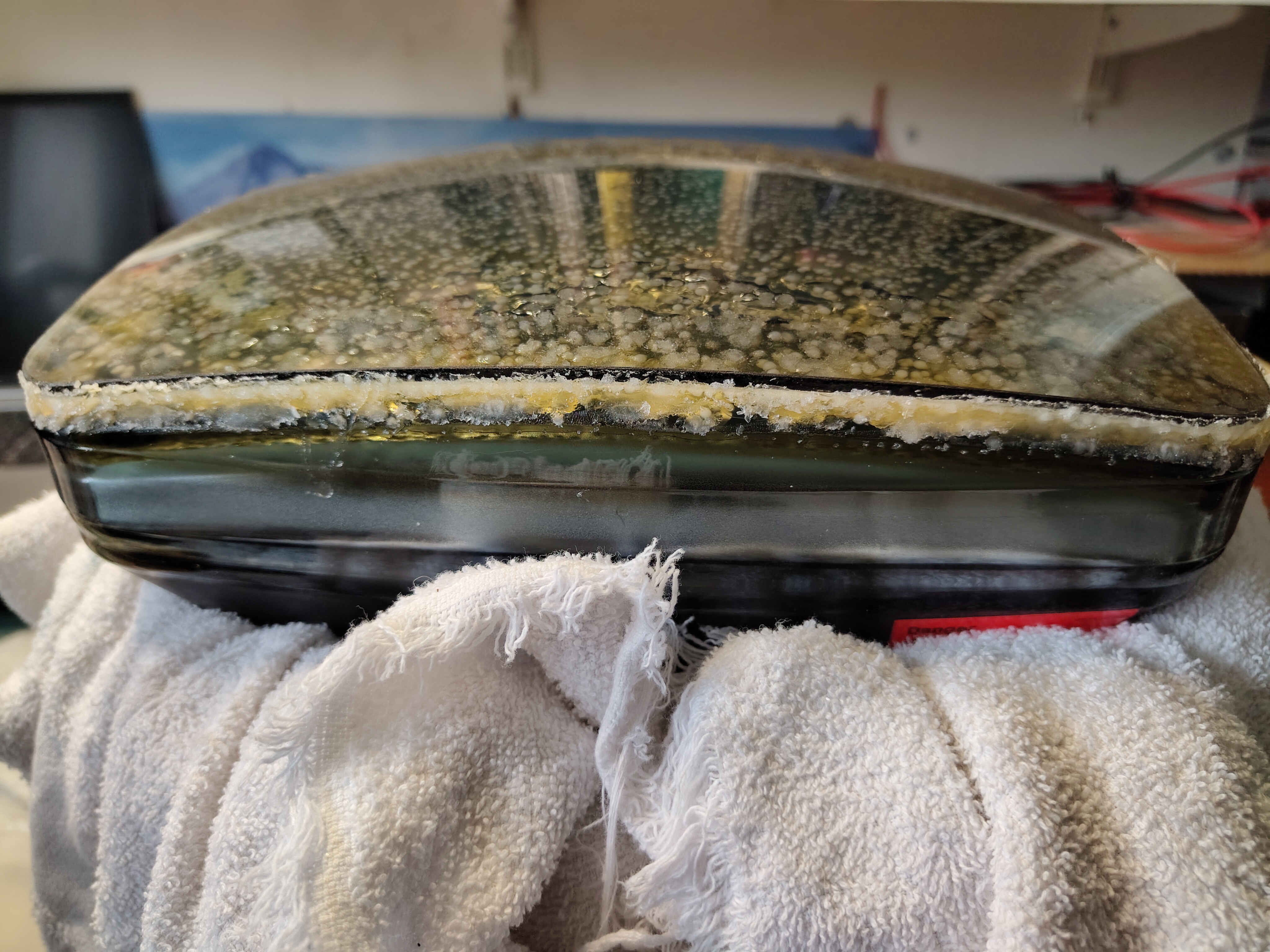
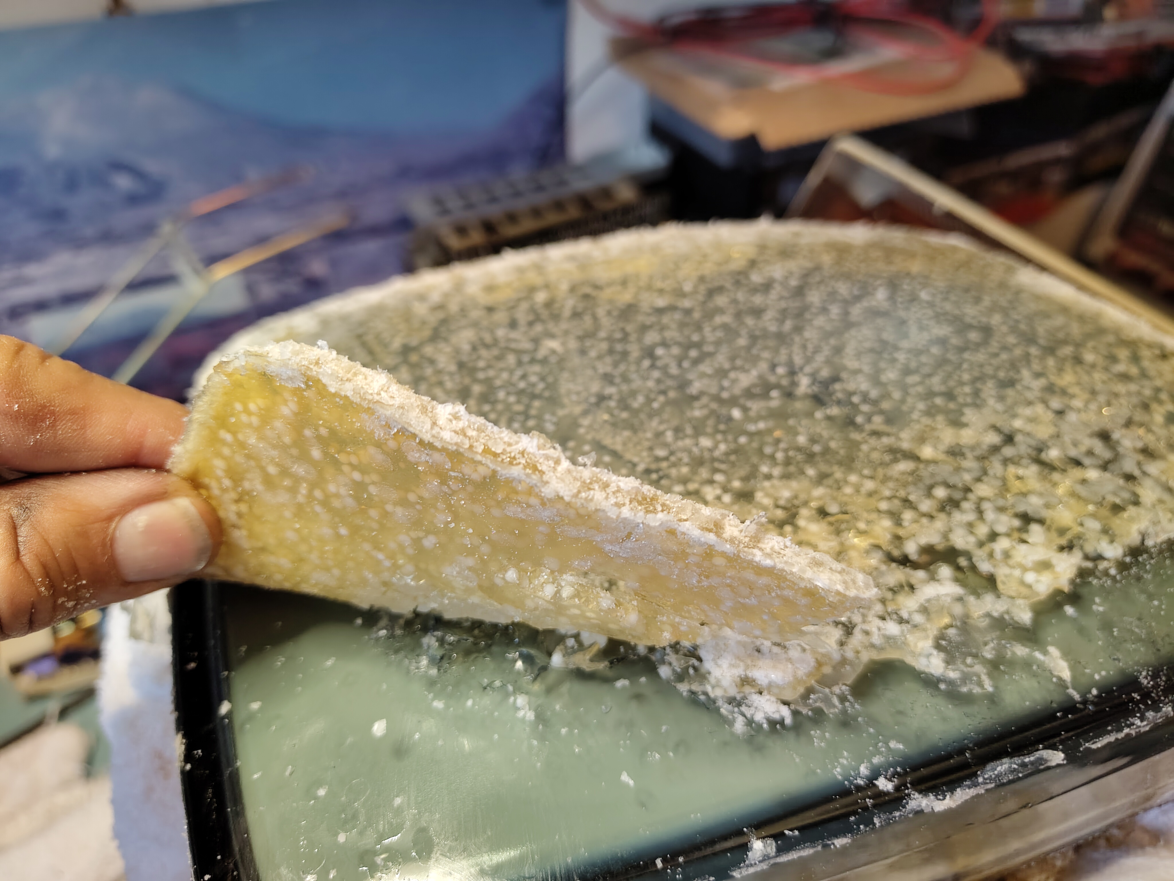
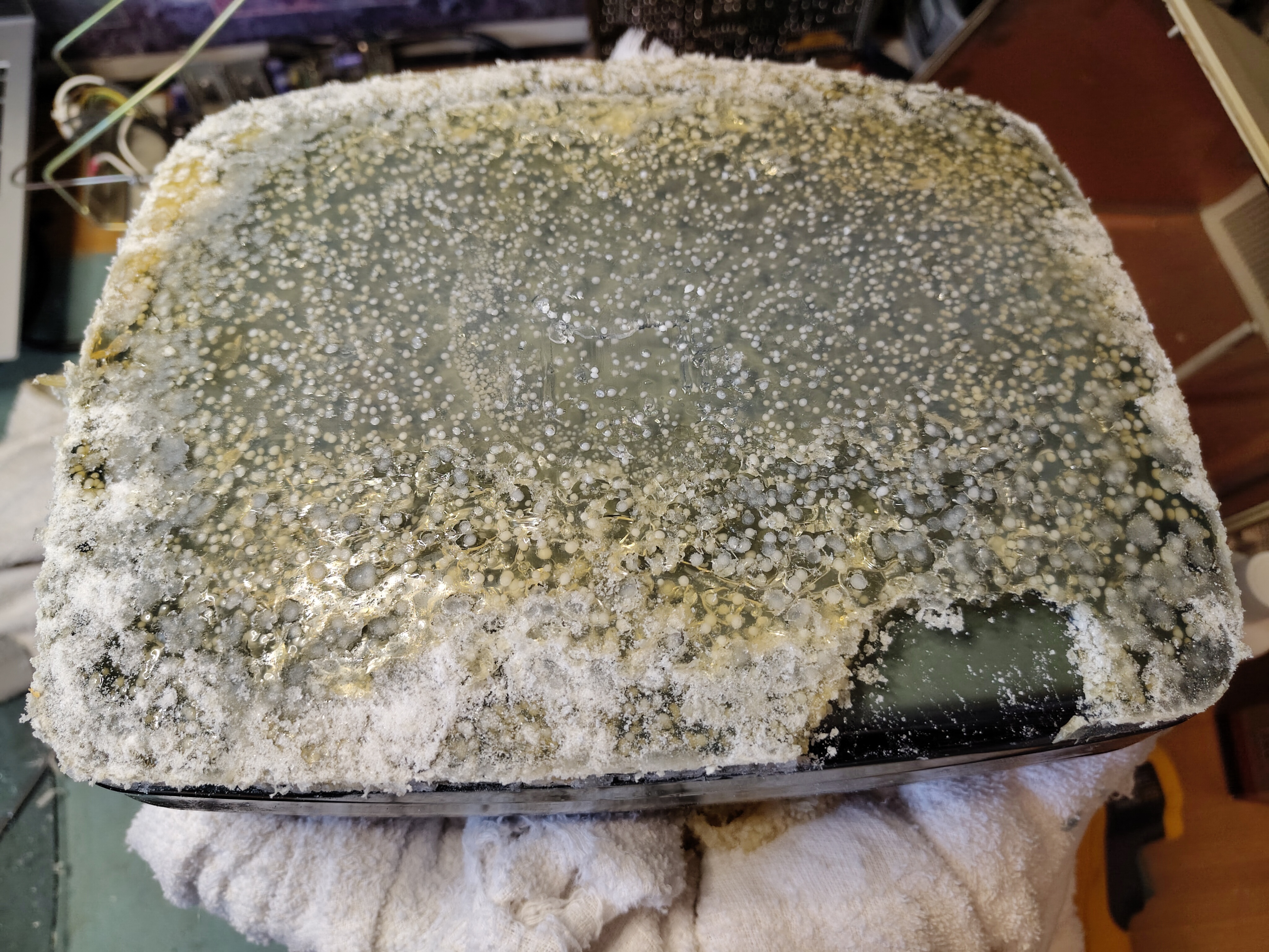
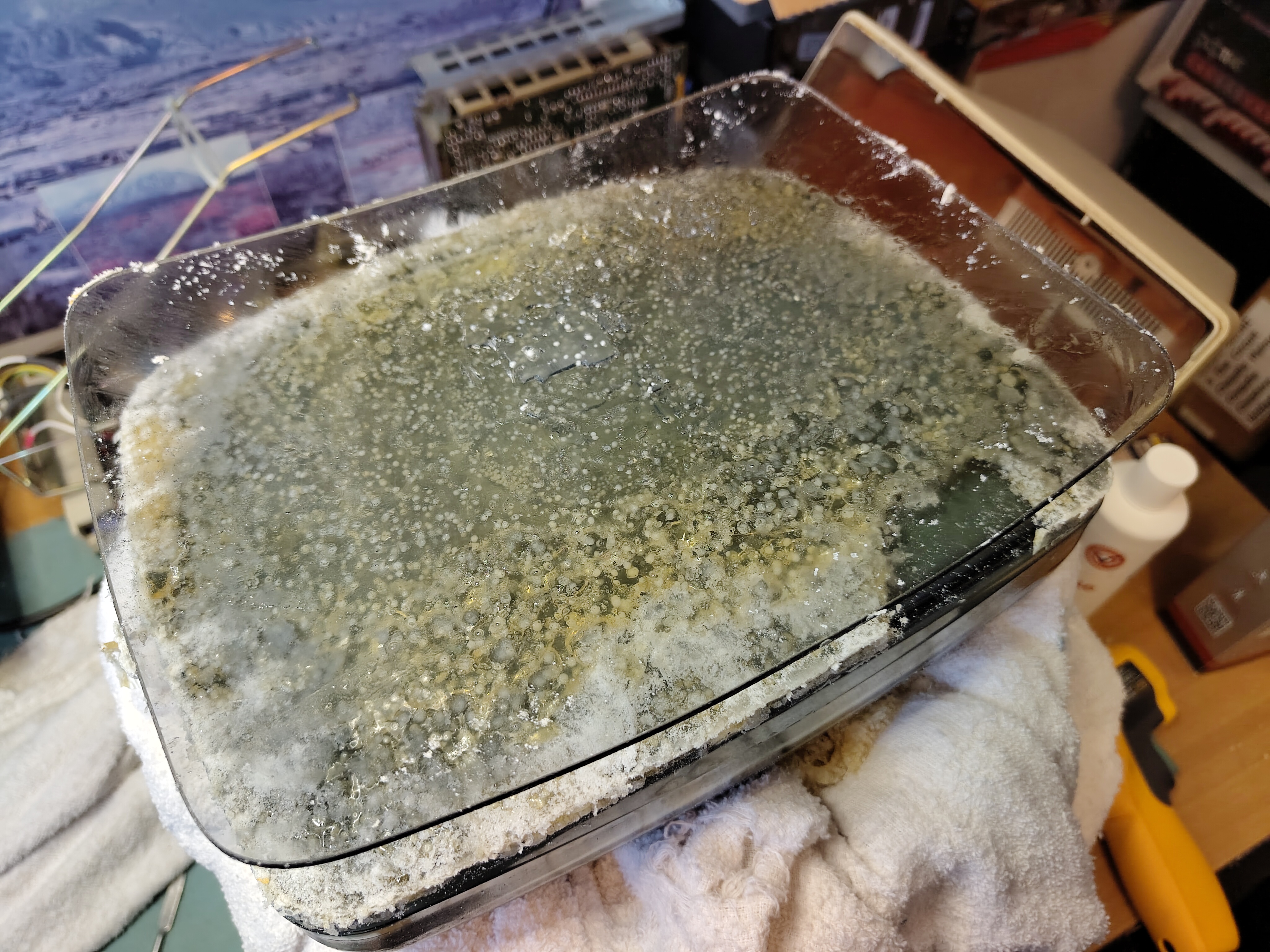
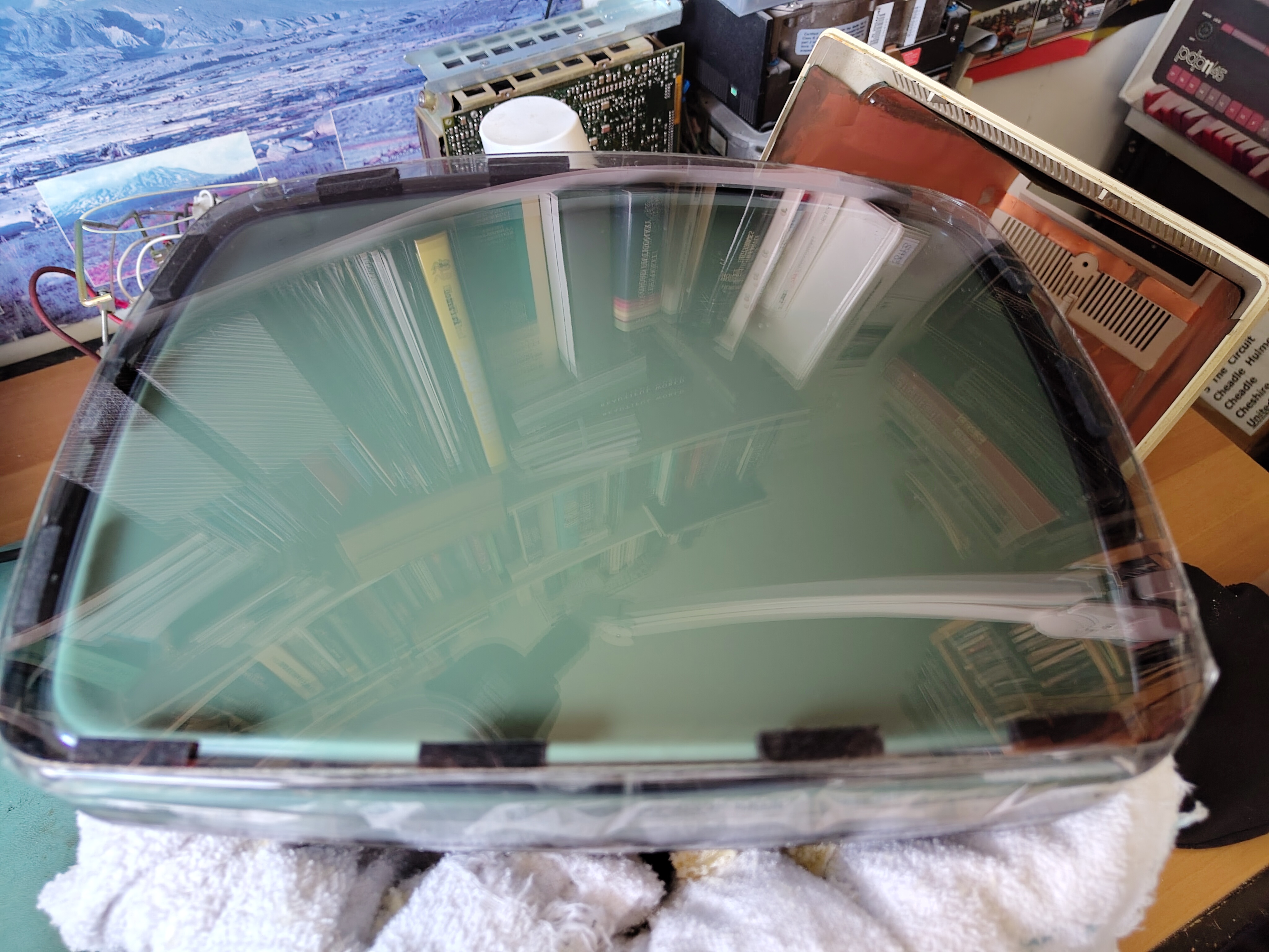
I used an ordinary hair dryer over the front glass to soften the glue underneath and gently worked away at removing the front glass. I found that the hair dryer got the front glass to about 65-70 Celsius and that was enough. I measured the gap between the front glass and the tube at 0.57mm with a calliper.
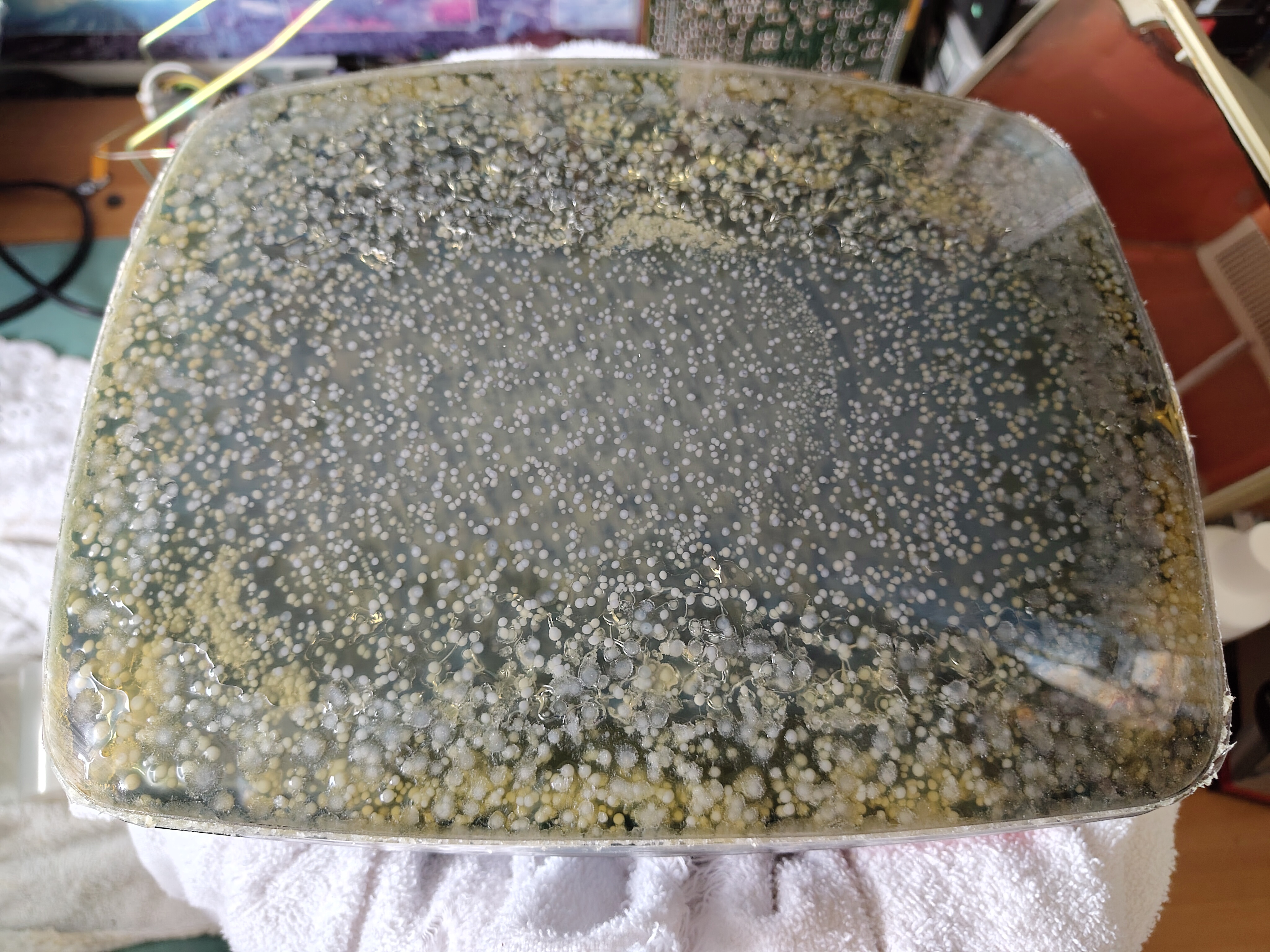
Some of the Glue Removed Behind the Front GlassSome of the Glue Removed Behind the Front GlasHole Where Glue Might Have Been InjectedSide View of the Deteriorated GlueThe Cataracts In Their Full Horror
Eventually the front glass came away and I was able to peel most of the glue off with my fingers.
The Tube After Removal of the Glue and CleaningThe Hole Possibly Used to Inject the GluePartially Removed GlueSide View of the GlueFirst View After Removal of the Safety GlassThe Safety Glass is Off
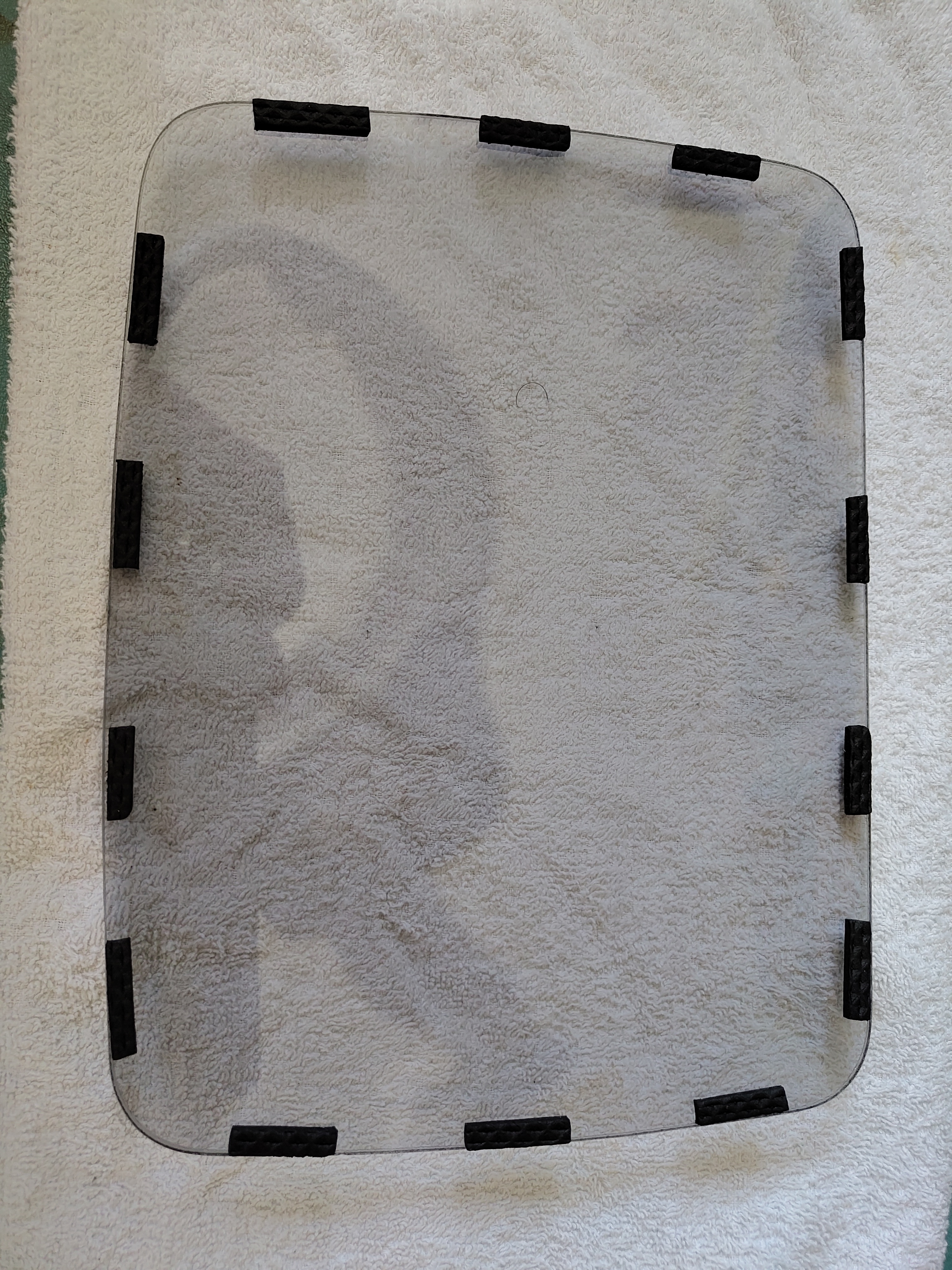
After careful cleaning I applied thin strips of rubber that had a self-adhesive on one side to the front glass. I placed it over the tube and held it in place with adhesive tape, which also serves to keep dust out.
The Safety Glass With Rubber Pads InstalledSafety Glass Re-installed
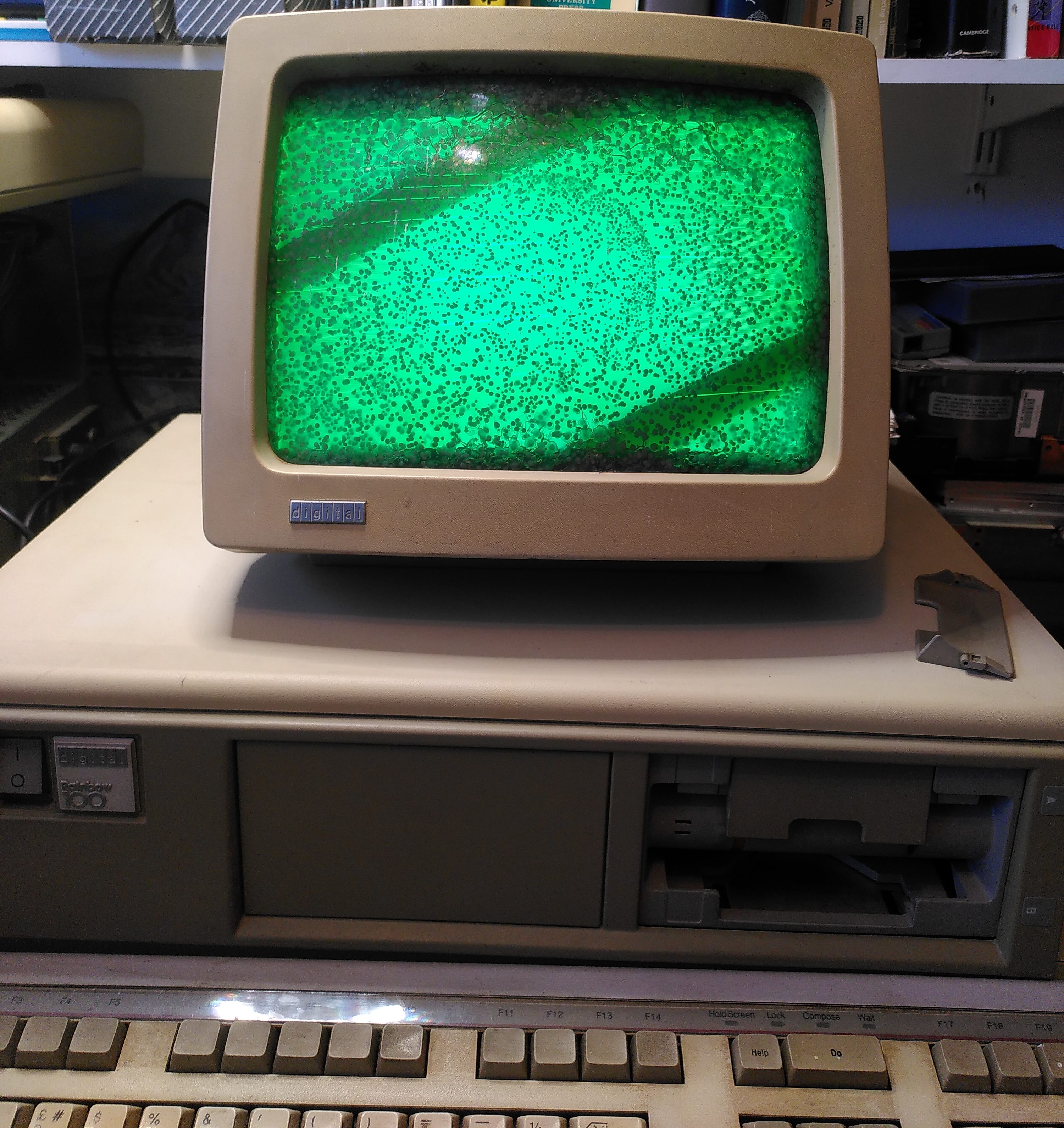
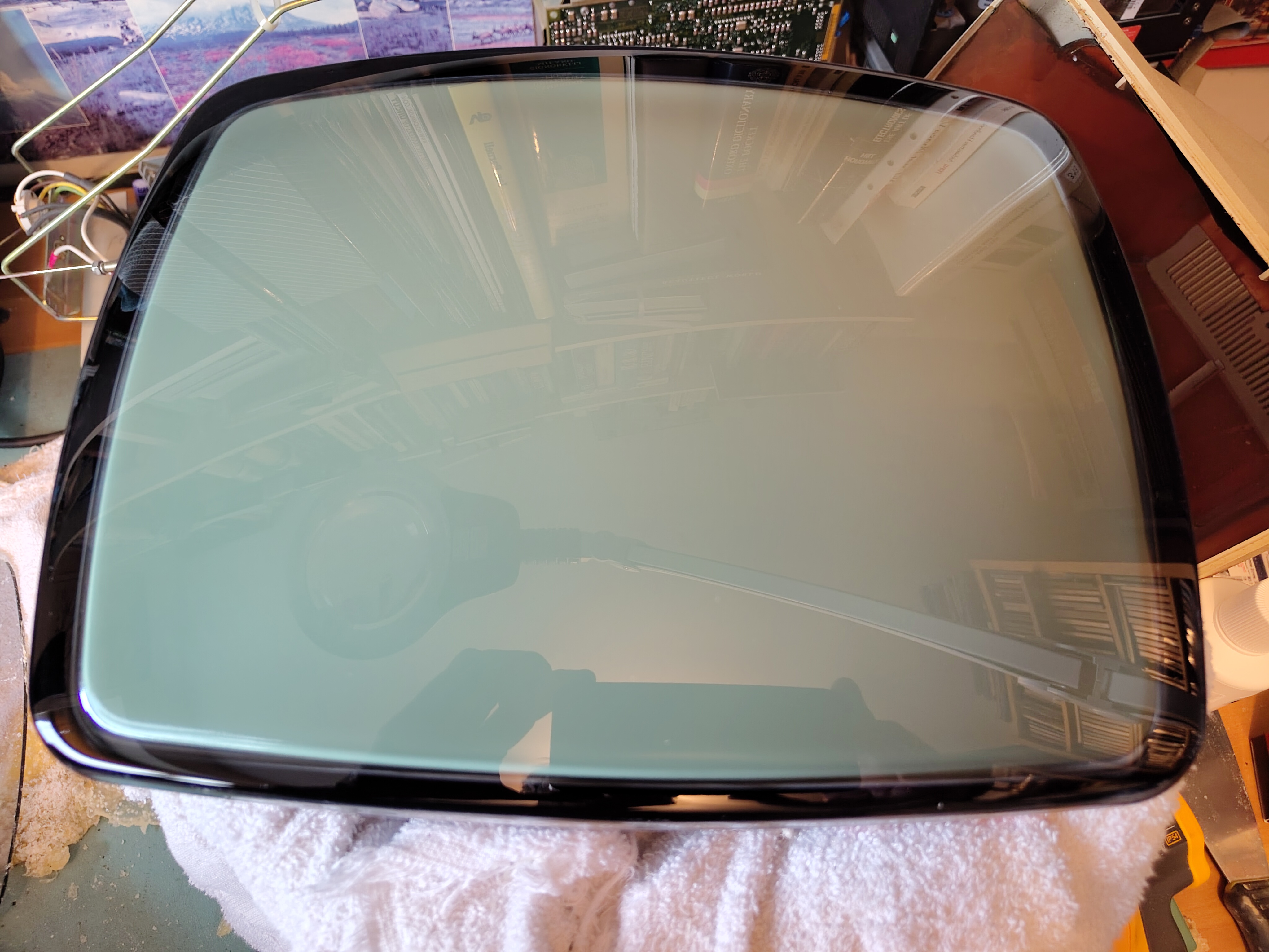
After reassembly the monitor looks good again.
VR201 After Cataract RemovalVR201 Working After Cataract Removal
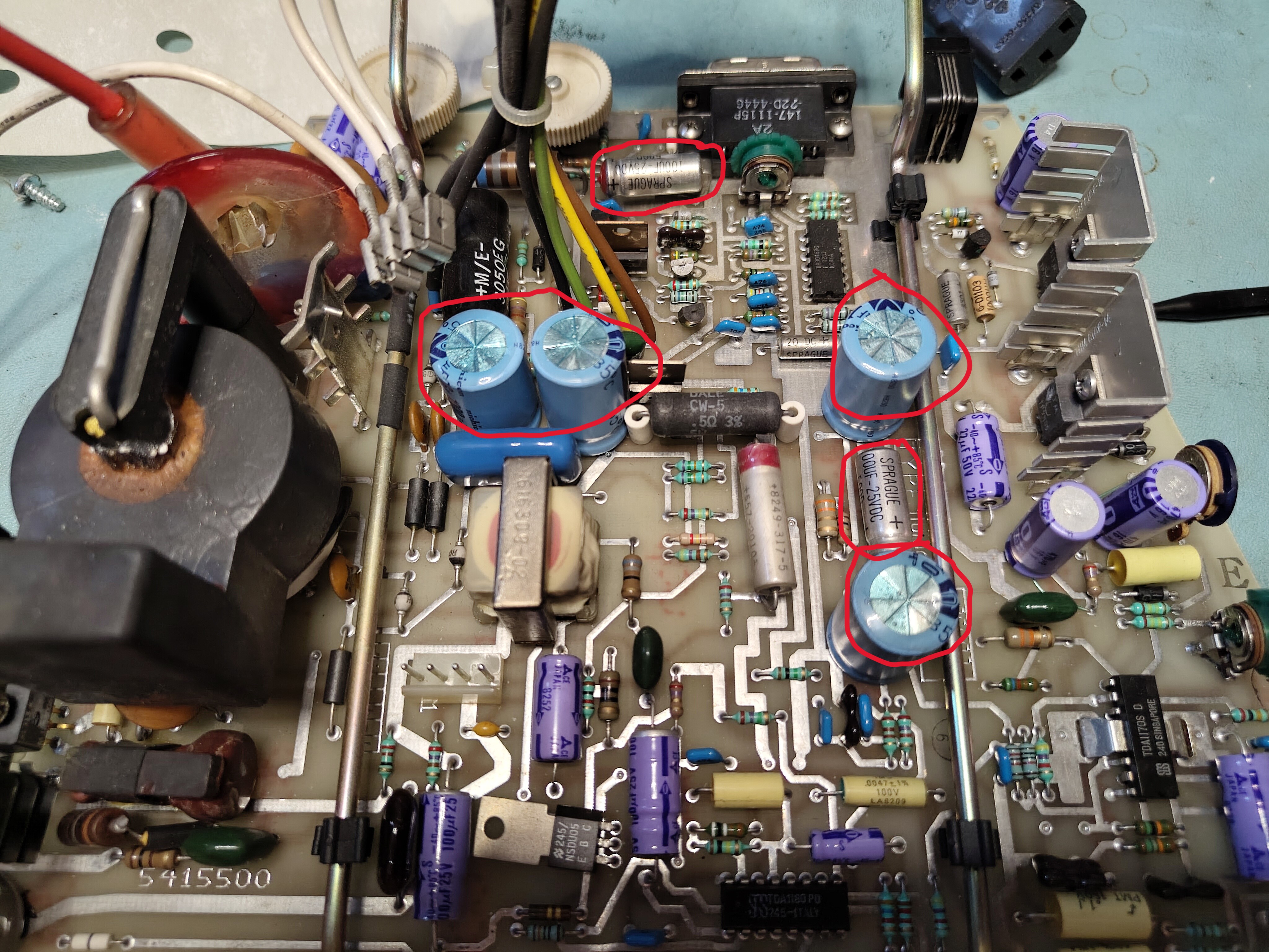
However I noted a slight shimmer in the display and struggled to get a bright display without the background being too bright. It looked like some of the electrolytic capacitors on the monitor board needed to be replaced. After examining them I found some had suspicious bulging or a high ESR, so I replaced C24, C30, C41 C303, C404 and C39 (as per the print set). They are the ones marked in the picture below.
Capacitors to be Replaced on the Monitor Board
After replacing the capacitors I put the VR201 back together again. The shimmer was still there, but it disappeared after a few minutes of operation. There is a faintly discernible vertical jitter, but very minor. Occasionally the monitor goes blank and a power cycle is needed. I don’t plan to look further at this for now.
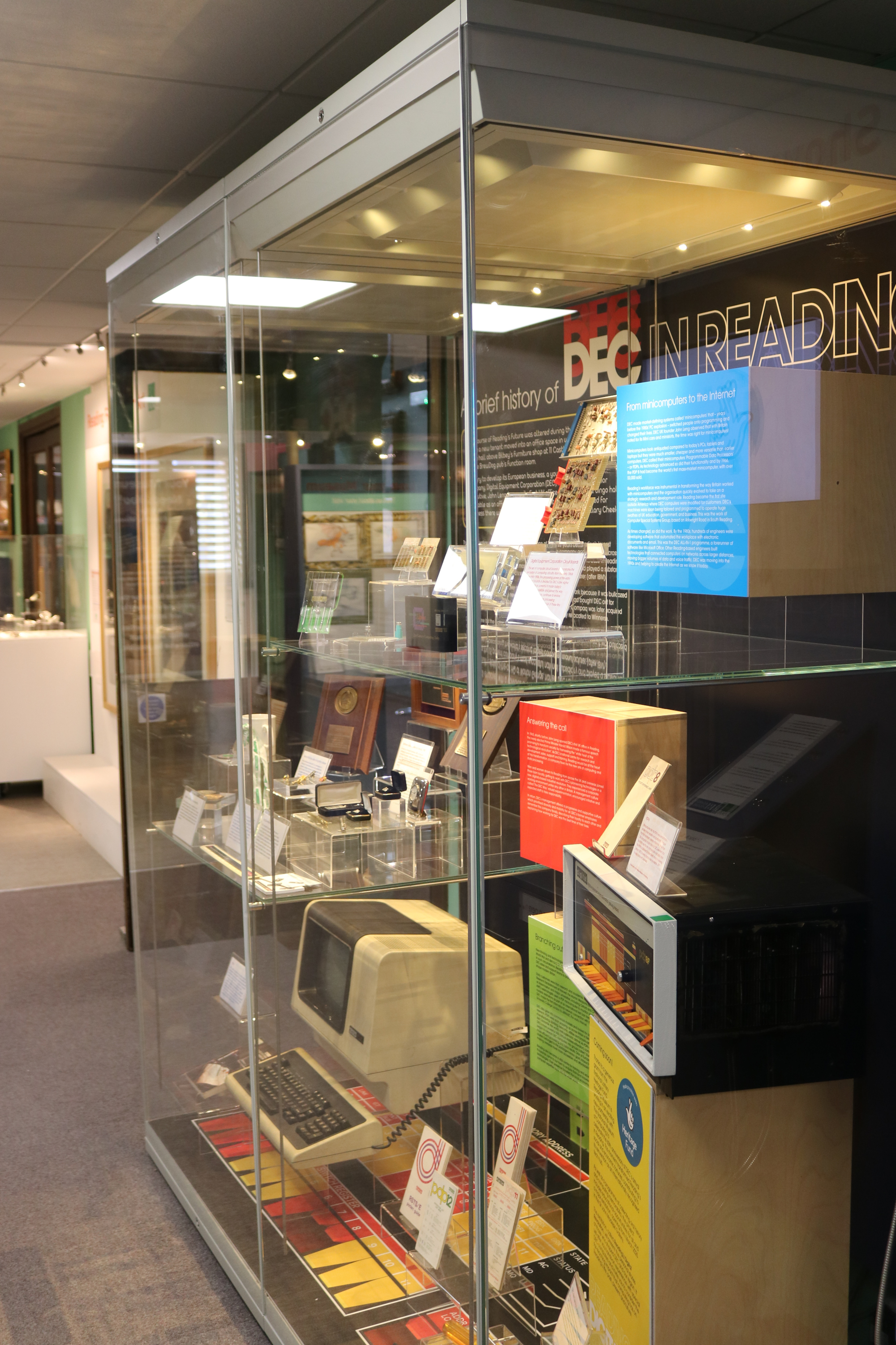
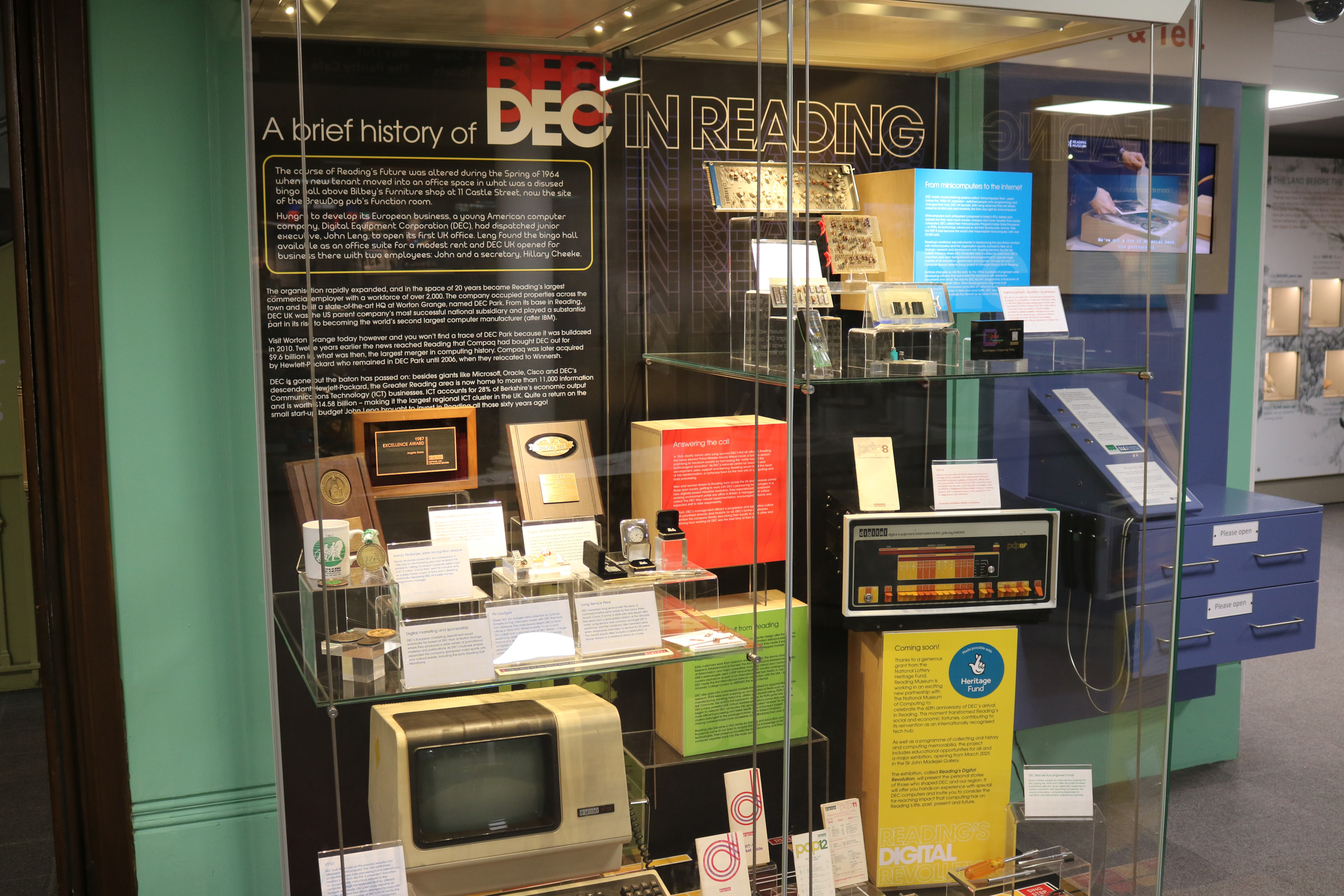
As part of Reading Museum’s Digital 60 event I was asked to loan my VT101. Some months ago the museum sent a driver to my house to collect it, he wrapped it up very carefully and duly took it away. Sadly this exhibition is about to end, but there will be a new one in 2025.
I thought I would post some pictures of the VT101 on display.
Here is the text of the label they displayed:
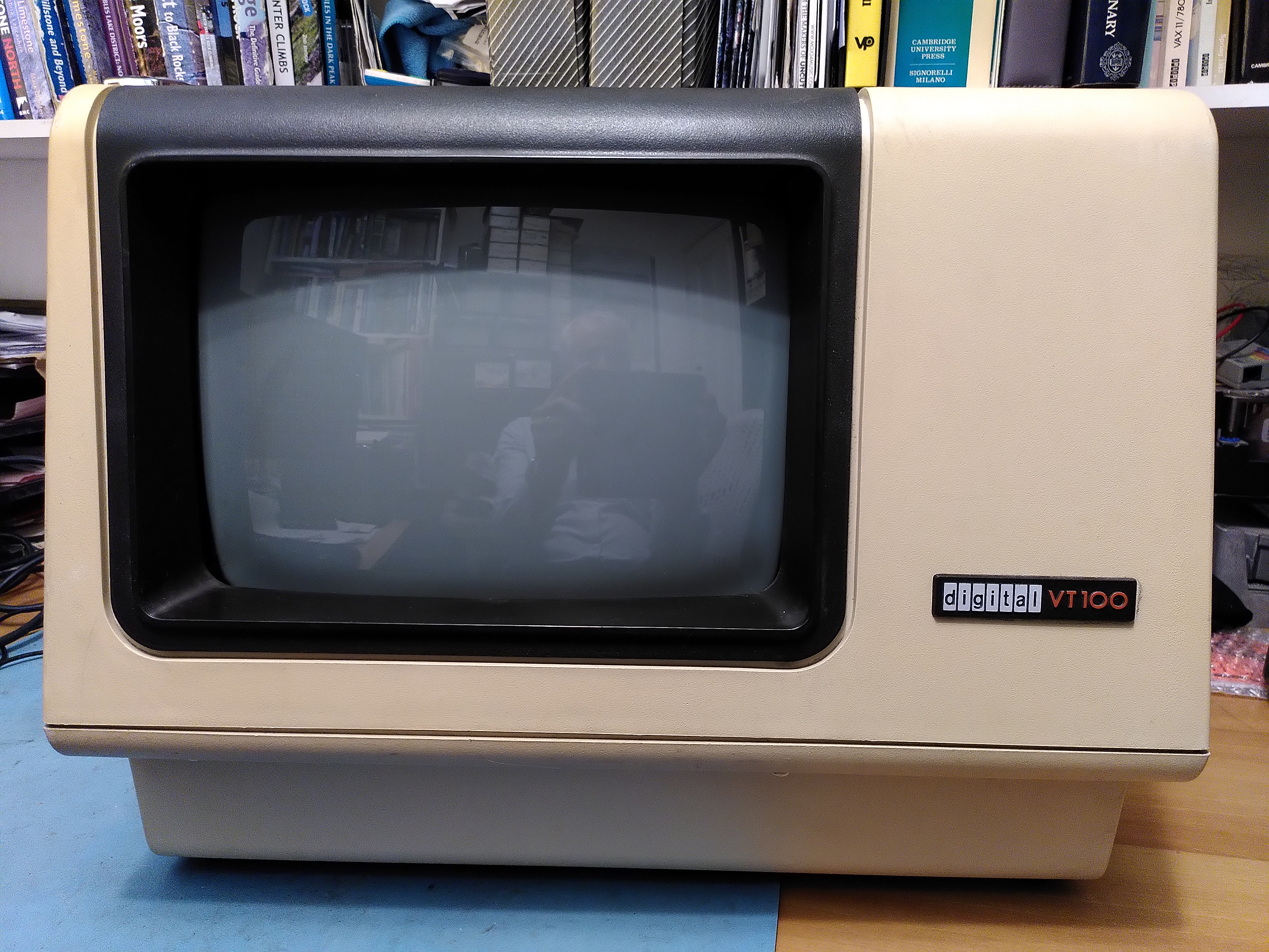
DEC built its success on the popular, versatile and affordable “minicomputer”. The mini performed computation and data processing but to interact you needed a terminal like this. It presented characters on a monitor with instructions relayed to the computer through the keyboard. Built for different budgets and needs, DEC’s terminals became an industry standard that others attempted to copy with mixed success. A member of DEC’s VT100 family, this VT101 lacked features such as printer connection, helping to reduce its purchase price.
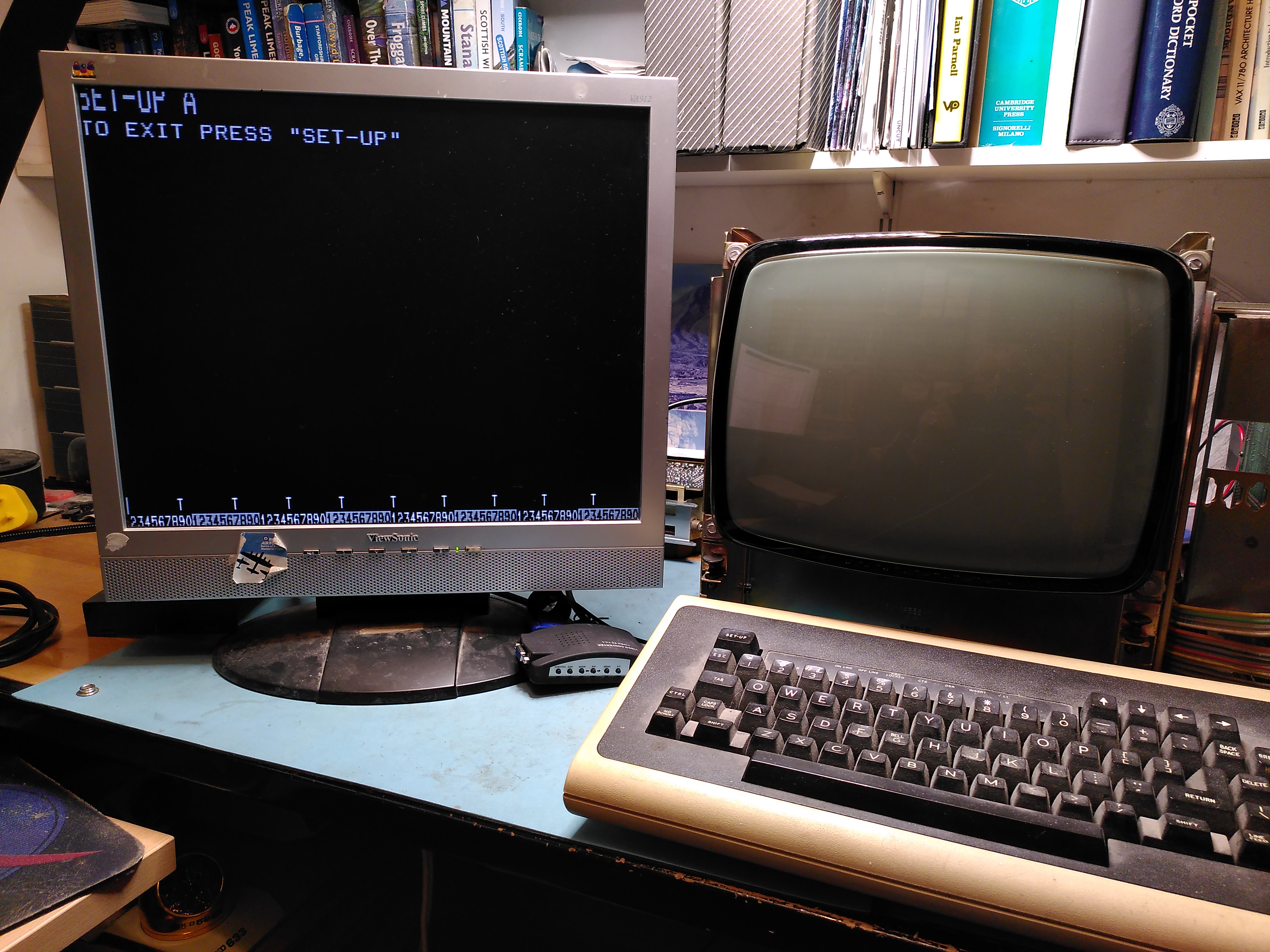
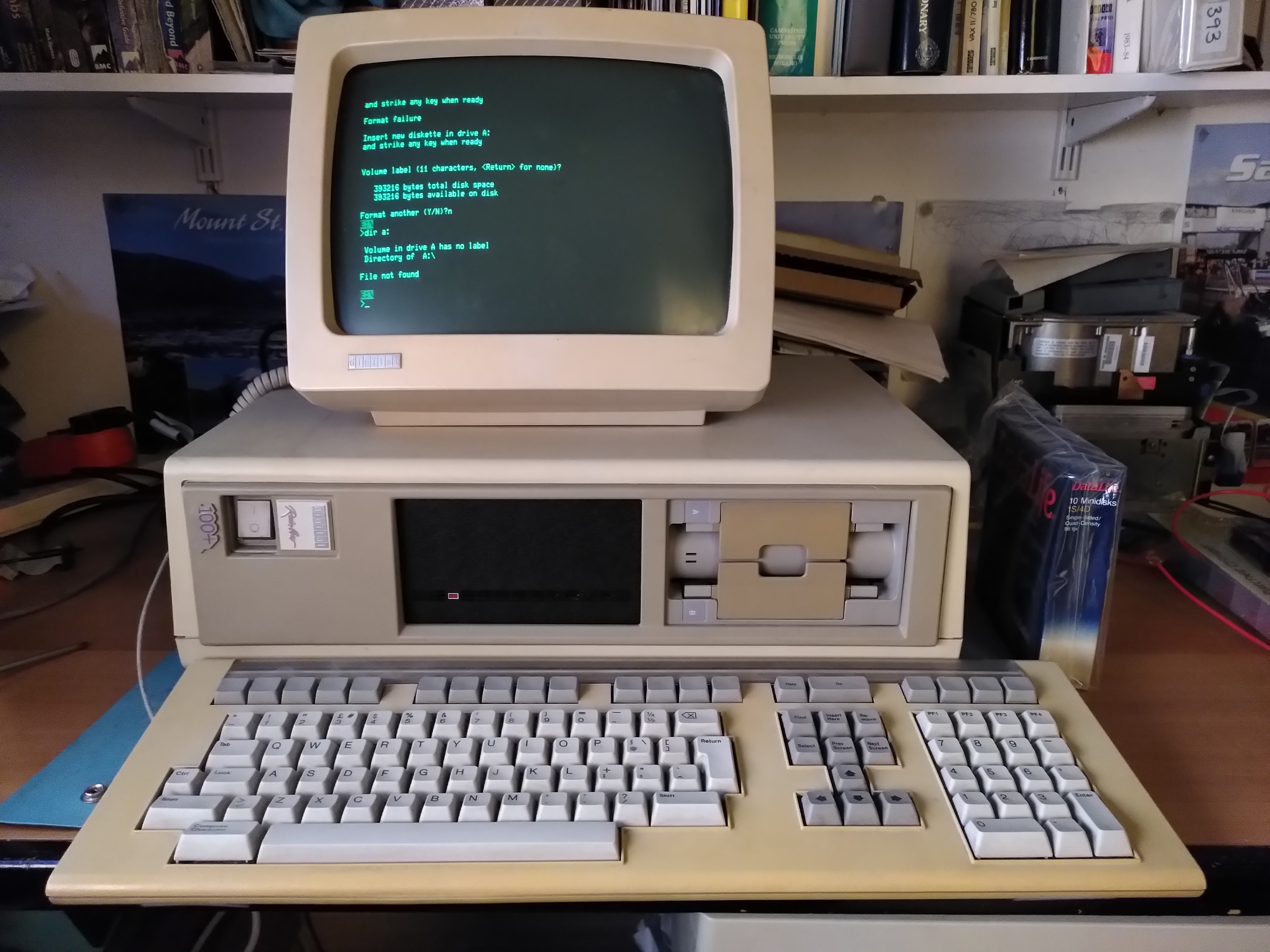
External Video on VT100 Using a Video Converter After Replacing the DC012
I have been making progress on restoring the VT100 I acquired some time ago. The RAM is now OK and the keyboard interface is working. However, I was still not getting any output on the screen and I know that the NVRAM is not working. I have obtained a replacement NVRAM chip but I want to fix the video first.
When I started to look more closely, the first thing I discovered was that the fuse on the monitor board for the +12V supply was open circuit. Using a bench power supply with current limiting I connected just the yoke and gave the board 12V. There was a faint glow from the yoke and it drew about 100ma. On advice I temporarily used a 12V car bulb in place of the fuse in order to test how much current gets drawn when the monitor board is fully connected to everything. It drew about 1.4A and the voltage on the output side of the bulb was 6.9V, so there was no dead short.
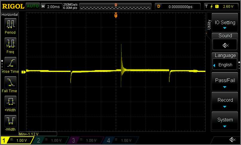
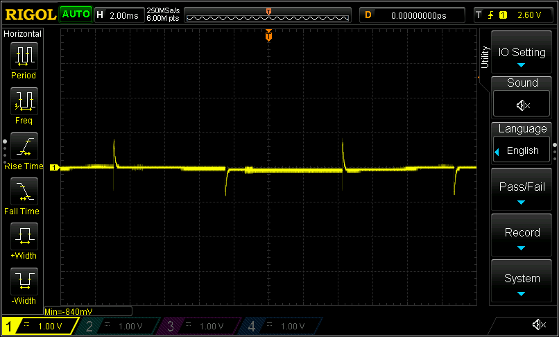
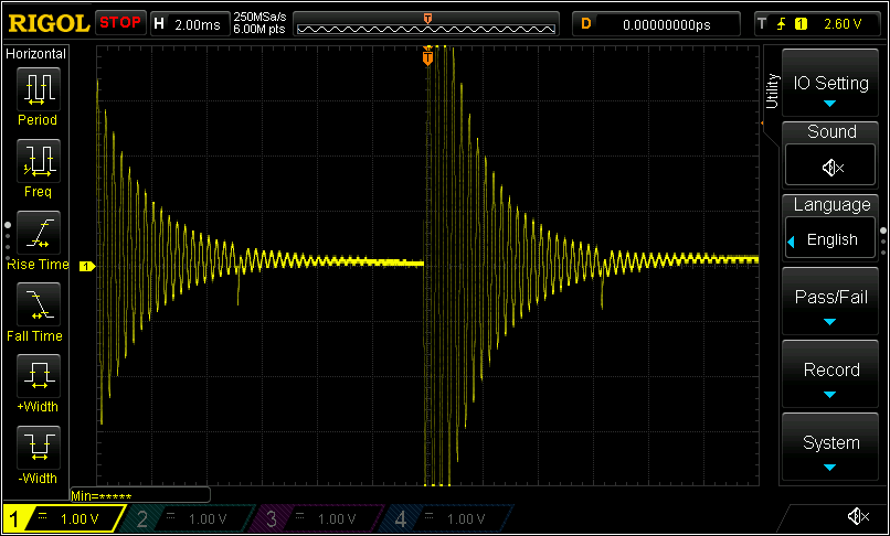
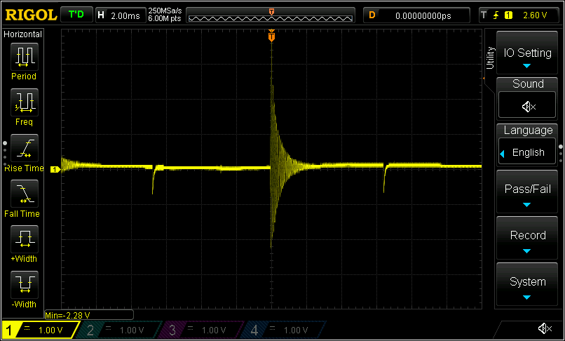
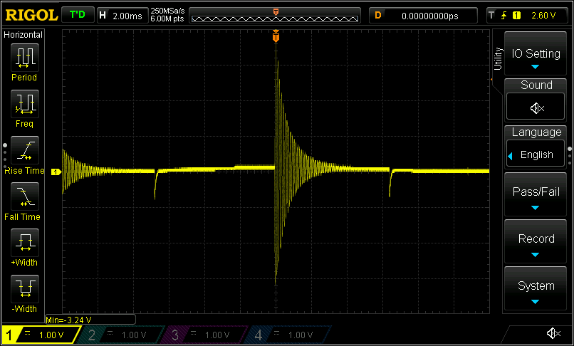
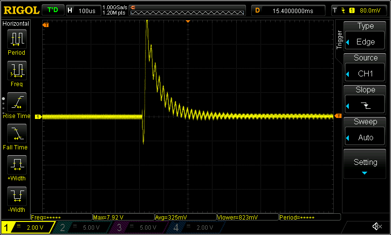
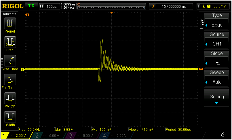
I also tested the flyback transformer with a ringing tester. Most of the windings seemed OK when compared to a VT101 that I have. One of the windings still rings, but not as much as the VT101. These are the scope traces for the two flybacks:
I tried to test without the car bulb acting as a current limiter. However, the yoke filament did not glow and I fancied I could smell some burning, possibly coming from the flyback transformer, so I switched it off very quickly. I fear that one of the flyback windings may have failed, but I don’t know.
On further advice I decided to connect an external monitor to the external video output on the basic video board. I found an old LCD screen that works just about well enough with a little video converter device I have. I verified it worked first with my working VT102 and I got a display. However, when I tried it with the VT100 I did not get the expected image. On startup I got some random looking patterns, and when it had finished starting up I got a blinking column down the left of the screen. I also noticed the smell of a chip that is getting hot, but I couldn’t locate it.
I checked that the DMA was retrieving the right data from the screen RAM. This seemed to be OK and the right data was being presented to the character generator ROM. However, my logic analyser doesn’t make it easy to check the validity of the ROM outputs. I could see though that pressing keys altered the output of E10, the Video Shift Register. It seemed to me though that the DC012 was probably outputting what it was being given, as something did get displayed and it did vary a little depending on what keys were pressed.
It was while checking the data sent to the DC012 that I realised that it was E10, the Video Shift Register, that was getting hot. In fact after a few minutes it would be too hot to touch. The same chip on the VT102 does not do this. I tried replacing E10, but the new part also gets hot. I am still not clear about the cause of this.
After a while I realised that the vertical flashing bar was just the cursor being displayed and being stretched the full height of the screen. I imagined that perhaps the first line of characters was somehow being displayed repeatedly across all lines of the screen, except that the characters I typed did not appear on later lines. After asking on the Vintage Computer Federation forums for advice I realised that perhaps it wasn’t the first line of characters that was being repeated, but the first line of pixels. I tested this by typing some different characters that had pixels at the top of the character cell, sure enough those pixels appeared across the full height of the screen. So now I knew that it was the first line of pixels that was being repeated.
The next thing to do was to check the Scan Count being output from the DC012 Video Control chip. This seemed to be either all zeroes or all ones. On the working VT102 it counts up as expected. I concluded that the DC012 must be faulty. It could even be why E10 gets hot, although the DC012 does not get hot.
Turning again to the Vintage Computer Federation forums, a very generous member offered to send me two DC012 chips. I took out the old one, replacing it with a socket, noting that the DC011 was already socketed. This fixed the issue and now I have the external video working, as shown in the image at the top of this post. I noticed that E10, the Video Shift Register, is still getting very hot and the new DC012 is a little warm too.
The current situation is the following:
I still don’t have an image on the VT100 screen as I removed the monitor board and have taken it apart. I think the flyback transformer has failed, but I can investigate this a bit further, knowing that the video signal is now correct. I am not hopeful though, because although the DC012 was producing the wrong image, the video signal itself was correct.
The NVRAM chip probably needs replacing.
The Video Shift Register, E10, is still getting very hot and I need to work out if this is normal.
In my last post VT100 RAM Fault I reported progress on fixing my VT100, getting past a RAM fault, but I left it with a fault where the keyboard constantly clicked the speaker. I knew the keyboard was OK because it works with my VT102.
The Basic Video Board communicates with the keyboard using RS232. There is a UART on the Basic Video Board and another UART in the keyboard. The firmware sends commands to the keyboard using a status byte that is described in the technical manual. The status byte controls the speaker click, the LEDs and the scanning for keypresses.
I wondered if the firmware was not operating correctly, perhaps trying to signal an error. I found a wonderful page that annotates the firmware really well. It looked like perhaps the firmware was getting into a loop trying to sound the speaker. The firmware uses a counter in the BC register to sound the speaker at the start and I could see from address traces that while it is doing this the vertical frequency interrupt is occurring. The interrupt routine saves the BC register on the stack and it looked like perhaps the RAM was not working correctly and corrupting BC. However some further analysis with the logic analyser showed that the RAM was working correctly at that stack location. While tracing the execution of the firmware I also found that it is detecting an NVRAM failure.
I moved on to look at what data the UART is sending out to the keyboard. I set up the logic analyser to capture the parallel inputs to the UART (labelled XD0-XD7 on the schematic) and triggered on the rising edge of LD XD. The data I saw being sent seemed completely reasonable. It initially sent 0xA0, which clicks the speaker on start up, and then it went into a cycle of sending 0x20 with the odd 0x60, which means it is turning on the on/off line LED and scanning for key presses. This seems perfectly normal and expected.
I then used the logic analyser on the UART in the keyboard to see what it was receiving. This data did not correspond at all to what the UART on the Basic Video Board was being asked to send, it was garbage. Clearly this implicated the UART on the Basic Video Board. I checked the components between the UART output and the final output on the keyboard port and they seemed OK.
Because I have jumped to incorrect conclusions many times before I decided I would do what I could to verify this. My Rigol DS1054Z oscilloscope is capable of capturing RS232 data. First of all I made sure I had it setup correctly by using it on a working VT102. I found that I needed to set a bit rate of 7866bps, I had to set the non-default polarity, and most significant bit first. With this I was able to capture reasonable data from the VT102, although it wasn’t perfect, the timing seems to vary a bit so I got framing errors after which the data would appear wrong for a bit and then correct itself. I also checked the clock signal to the UART on the VT102, it was variable, sometimes around 126KHz and sometimes 106KHz, which I guess accounts for the framing errors I saw.
I then used the oscilloscope on the non-working VT100. The clock signals to the UART mirrored those of the VT102, but the data captured by the oscilloscope being sent down the wire was completely different.
I also tried to use a HP4957A protocol analyser, but this wouldn’t let me set a custom bit rate, so I was not very successful with it.
At this point I decided I didn’t have much to lose so I replaced the UART (marked D3-6402-9) with another one.
I am pleased to report that this cured the constant keyboard clicking. So now I have two problems left. The main one is that there is nothing displayed on the screen, I don’t see any glow from the cathode on the CRT, so possibly there is a fault on the video monitor board. This will be the next thing I look at. The other problem is the possible failed NVRAM, but I think I will look at that if I can fix the lack of a display first.
I acquired a VT100 a while back. It was just the video unit, without a keyboard, but I have a couple of keyboards for my VT101 and VT102, so I would be able to use it once I had it working.
My first job was to inspect it, particularly the power supply and the video monitor boards. It looked like some parts had been replaced on the PSU and there was a track that had been cut. The result does not match the schematic, but a friend has a similar situation with his VT100, so I was not too concerned. I also found that the heatsink for one of the 7812 regulators (Z2) was not properly attached with a screw, so I added a screw.
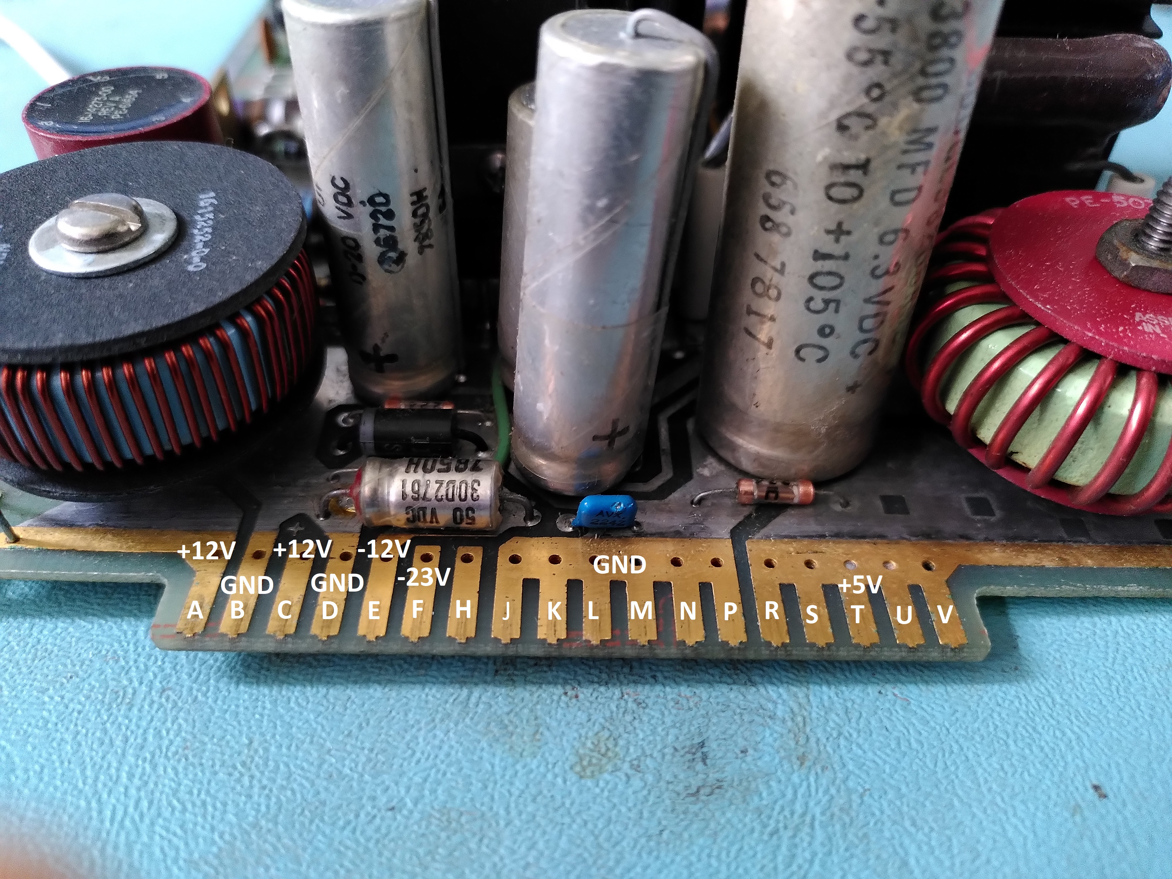
I then decided to reform the two big capacitors in the PSU. My bench equipment only allows me to go up to 60V though, which they did without issue. Given that they were OK up to that point I decided to test the PSU as a whole on the bench with an artificial load, just to be sure the whole thing was working OK. The picture below shows the connector marked up for which output is which.
The PSU tested OK for voltage and ripple. Except the -23V output which went to -31V. However, I am told that this output is pulled to -23V by two Zener diodes D2 and D3, as shown on the schematic on page 14 (B4-C4) of MP00633_VT100_Schematic_Feb82.
The apparently unused pin H of the PSU board connector turns out to lead to a cut on the track and patch wires, so there is clearly an ECO that is not shown on the schematic.
I also decided to replace the electrolytic capacitors on the video monitor board, in the interest of avoiding damage to parts that are difficult to replace (especially the flyback transformer, although I don’t know if the capacitors could cause it damage if they were bad), and also in the interest of getting a clean stable image. I did not replace the non-polar capacitor mainly because they are hard to find. I also took note of this and changed C439 from a 7uF 6V part to a 100uF 100V part.
At this point I was ready to try turning it on. Of course it was a major disappointment that there was no life from it, but I guess not totally unexpected. Nothing on the screen, no beep, no LEDs lit up on the keyboard, nothing.
I went through a number of troubleshooting steps to trace the issue, following some troubleshooting steps in the Technical Manual. I could see that the DC012 video processor control chip was permanently asserting the interrupt line and not generating any DMA HOLD REQUESTs. I wondered if this might be because the firmware hadn’t got to the point of initialising it, perhaps because of bad ROMs. I dumped them with help from my friend at 9track.net (a device to allow different Chip Selects to be used) and they looked fine, matching the ones posted here. Only one of the ROMs is posted on 9track, I dumped the other three. The all the dumps plus the disassembly of the first one are here.
After disassembling the first ROM I used a logic analyser to see if the 8080 was executing instructions correctly. I was able to see that it was following the instructions in the ROM, so the 8080 CPU is fine. I could see that it was supposed to send the self-test status to the keyboard LEDs, but for some reason these would not light up on the keyboard. One of my keyboards has a suspect cable. I wasn’t sure if it was down to that, so I put the logic analyser on the UART to see if I could see what it was sending to the keyboard. I was able to see it sending the codes to light all the LEDs, then sending codes indicating the ROM tests and finally the RAM test. It never sent another code after the RAM test, so I concluded that the RAM test was failing.
Looking at the disassembled code I found the RAM test code and could see that it writes 0x00 and then 0xAA to every location, I think it also tests 0x55. After a few false starts in trying to observe the RAM test with my logic analyser I was finally able to see the reads properly by triggering on the rising edge of the MEM RD pin on the J1 connector. This showed me that the reads stopped at a particular address, indicating that the 2114 chip labelled E51 in the schematic was returning a A when it should be returning a 0.
Initially I misidentified this because I thought it was a misread of the 0xAA, however it turned out that it was a misread after checking that the initial 0x00 could be read back, it was reading back 0x0A. It is a bit suspicious that it was always returning 0xA in the lower nibble.
Once I replaced the suspect chip the RAM test started to pass. I could also see from my logic analyser that the interrupt routine which clears the vertical frequency interrupt is invoked at 60Hz. So the RAM test is now passing.
Plugging in the keyboard, I now get a beep and the ON LINE LED lights up. However a few moments later all the keyboard LEDs come on and keyboard beeps continuously. The screen also remains resolutely blank.
I previously posted about the failure of the H7842 power supply in my DEC Rainbow. I reported that after replacing some parts I was getting an overcurrent detection in the -12V output. This was under bench test conditions using a bench PSU to power the startup circuit.
I did a lot of tests, comparing a working spare with the failed PSU, but I just could not find a reason for the overcurrent detection to be wrong. Strangely, that problem disappeared after a time. It has been suggested to me that the test conditions were not really representative enough of real conditions to be reliable, and that even an increase in temperature with the arrival of spring and summer might have been a factor. I decided to ignore the problem for now as it has gone away.
At this point I could try once more to see if the PSU would now work. As a precaution I used two 100W filament bulbs in series with the mains input as a current limiter, to make sure that things wouldn’t go too badly wrong if it didn’t work. I attached a dummy load to the 5V and 12V outputs. In a working PSU this causes the 100W bulbs to pulsate and never to go very bright. However in my bad PSU they shone much more brightly, there was no pulsing and the DC outputs stayed at zero.
I checked the supply to the startup 7812 regulator. It was only about 3.5V, so there was no way that the PWM was going to work or control the chopper transistor. In the same conditions this voltage was much higher on the working spare. I wondered if perhaps the startup transformer had some shorts. This seemed to be borne out after I lifted the diodes on the outputs of the startup transformer, because they tested fine.
However, on receiving further advice, I looked at the mains bridge rectifier. On removing it I found that it had two pins shorted together. When I tested the startup transformer with the rectifier removed and also all the diodes on the startup transformer output removed, the startup transformer output was 24VAC. So the startup transformer was OK. I think the rectifier must have been shorted when the main chopper transistor blew up.
I replaced the mains bridge rectifier with a new 600V part and the power supply started to work. I tested it first with the 100W bulbs to be sure, but when that went OK I took them out. With a dummy load the PSU had reasonable ripple and the voltages were correct.
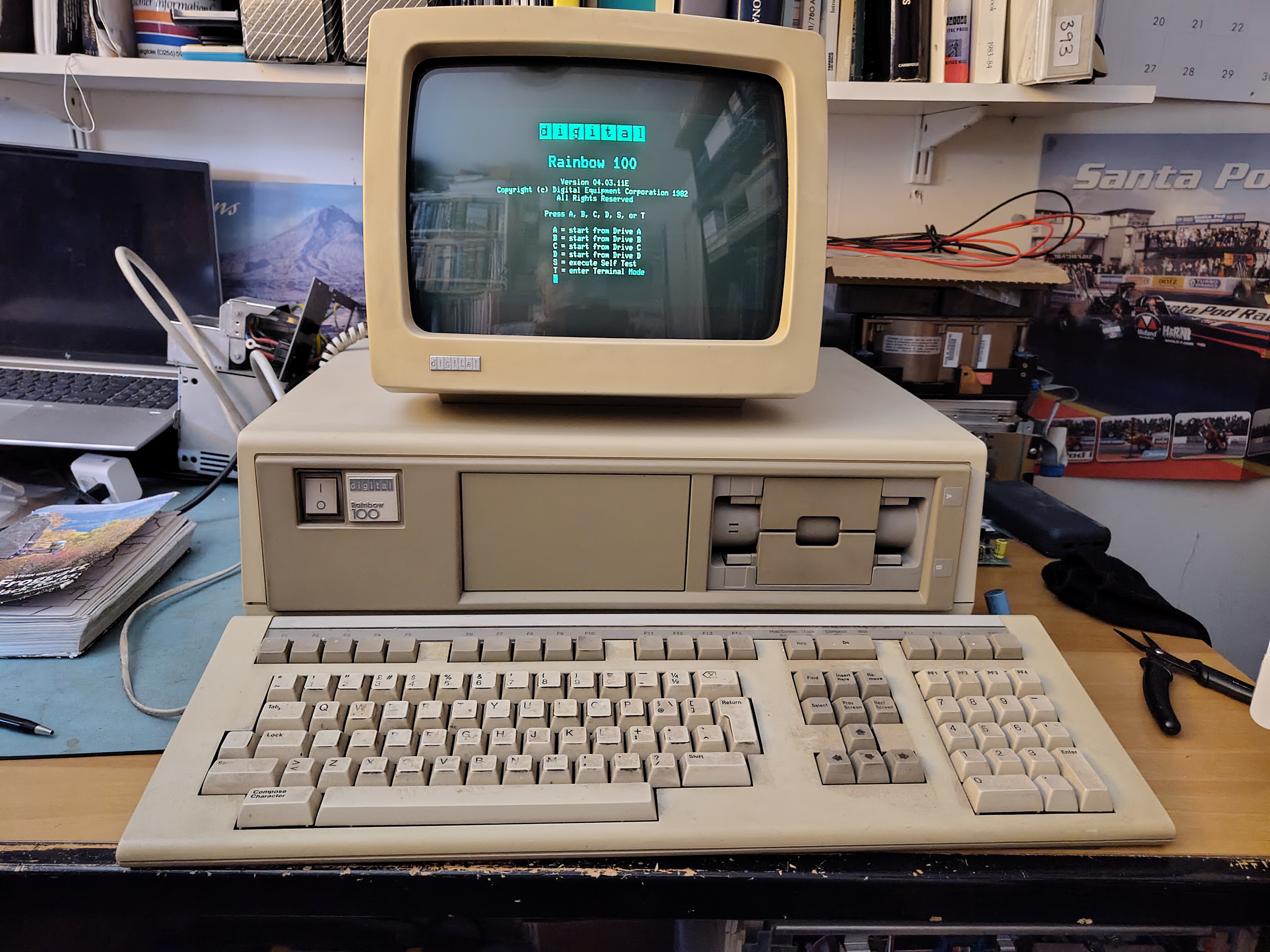
I reassembled the machine and it ran perfectly. The picture at the top is of the Rainbow running once more on its original power supply.
I would like to thank the people who offered my so much advice, without whom I would never have got this fixed.
The badges are on their side because this was installed in a vertical enclosure.
A couple of days ago, I received a request to format some RX50s in one of my Rainbow machines. So, I got this one out to check that it still works. I was happy that it just powered up fine. I went off to search for some RX50 diskettes to check the floppy disk drive with. When I came back the machine was silent. It had powered itself off. There was a vague burning smell and the circuit breaker on the back had popped.
Not knowing if there was perhaps a short in the machine or a problem in the power supply, I disconnected the fans, the floppy disk drive, the hard disk drive and, probably foolishly, I applied power again to see if the machine would work. At this point there was a bang and a flash in the power supply.
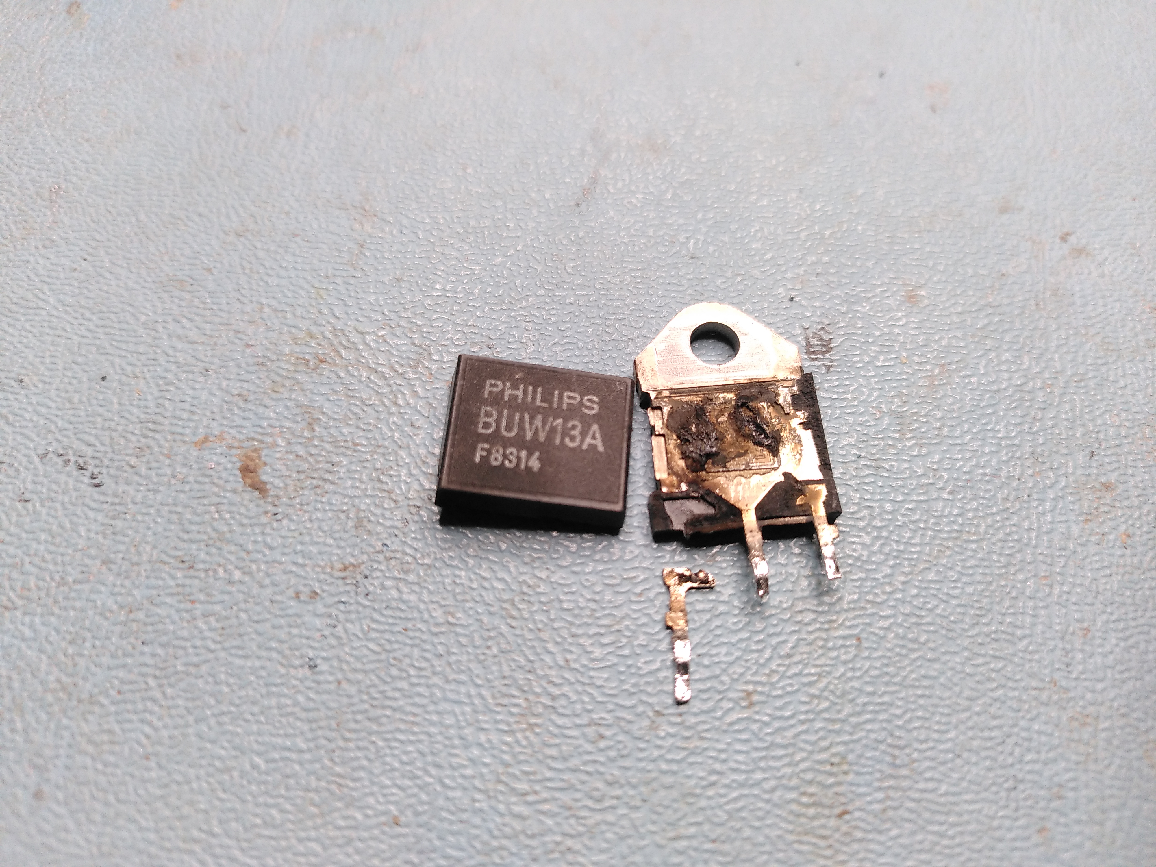
On opening up the H7842 power supply I found that one of the transistors had completely disintegrated. It looks to be the main switching transistor.
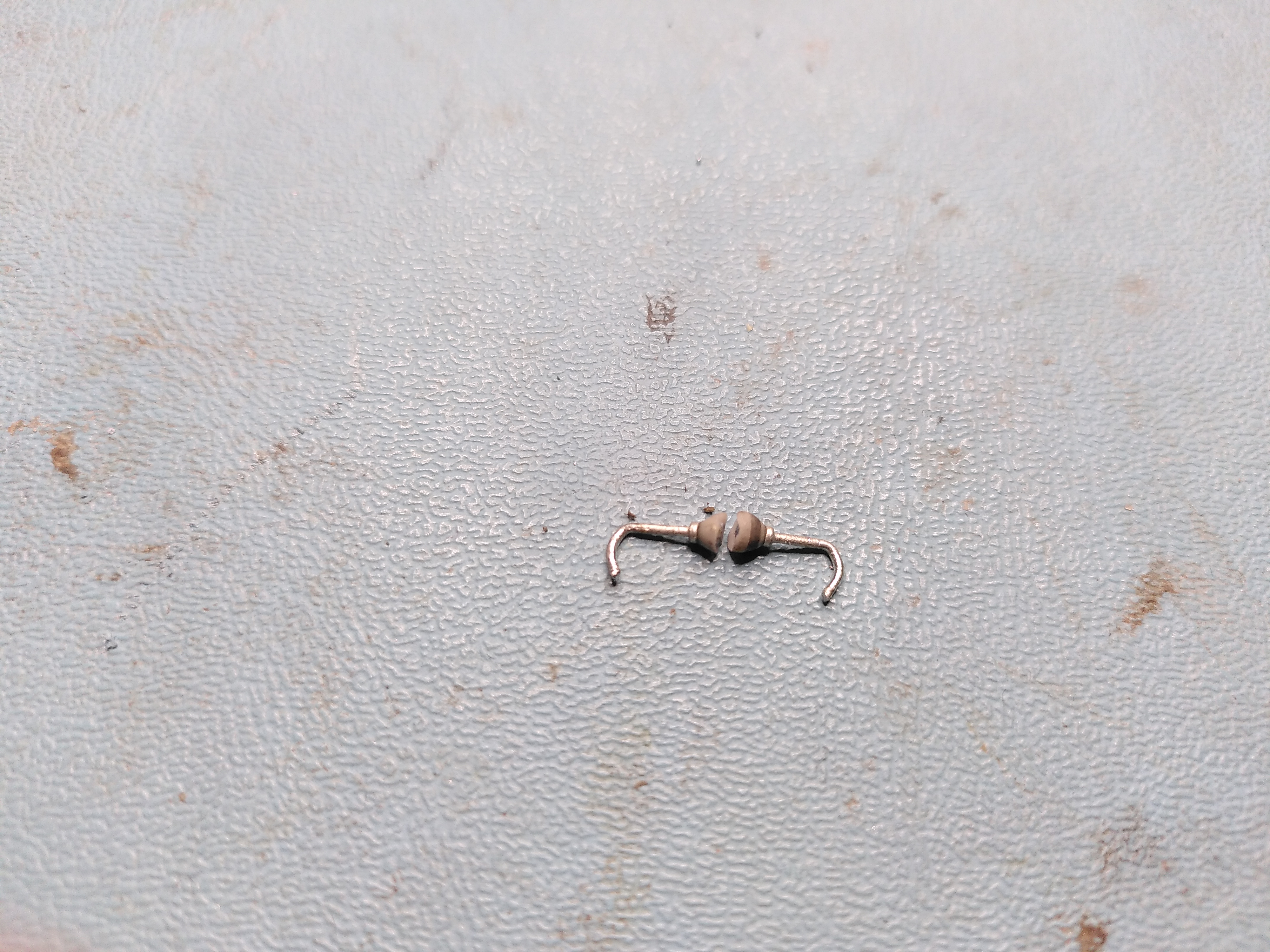
Given that before the transistor blew up there had clearly been another failure somewhere else, I tried to find the original failure. There were no obviously damaged parts, so I just probed around near the transistor for any parts that were open circuit or short circuit. I found a diode connected to the base of the transistor that appeared to be short circuit. So, I decided to lift one end to check it. As I de-soldered one of the leads, the diode broke in two. So clearly the diode was either damaged by the failure of the transistor, or it was the cause of the failure. This is the diode:
Tony Duell has reverse engineered the schematic for this power supply here. The transistor that failed is the one on sheet 2 labelled BUV48A and the failed diode is the one connecting the base of the transistor to the transformer and in parallel with a 2.7R resistor. I obtained a replacement BUV48A. I couldn’t identify the diode, the markings looked like they said “D610” but I couldn’t be sure, so after advice from the cctalk list, I replaced the diode with a UF4007. I also discovered that the 7812 regulator (sheet 1 of the schematic) had failed, so I replaced that too.
On further advice, I tested the control board in isolation by using a bench power supply to put 15V into the 7812 regulator mentioned above. On a working PSU you can see the PWM (Control Module Sheet 2 on the schematic) producing a signal that turns the chopper transistor on and off and the current draw from the PSU is about 87mA. However, the PWM was not producing a signal on Output A and the current draw on the bench PSU was about 140mA. Furthermore the 5.1V reference voltage was actually 9.75V. So the PWM was faulty and I replaced this with a UC3527AN.
Despite replacing the PWM, it still did not operate. I discovered that the Shutdown pin on it was being asserted. I traced this to an LM339 comparator (E3 on Control Module Sheet 1 of the schematic). The output was incorrect given the inputs.
I replaced the comparator. However the E3c output is high and so it is shutting down the PSU. Tony’s schematic seems to have some errors on it in this area. Reverse engineering the circuit it looks to me like E3c has the ISense -12V- and ISense -12V+ as inputs, so the comparator marked E3d on Tony’s schematic is actually E3c.
So, the problem now is that there appears to be an overcurrent in the -12V circuit. This is being detected even when I use a bench PSU to supply the Vstart signal only by applying 15V to the input of the 7812 regulator on PSU Sheet 1 (page 2 of the PDF).