| Make | Digital Equipment Corporation |
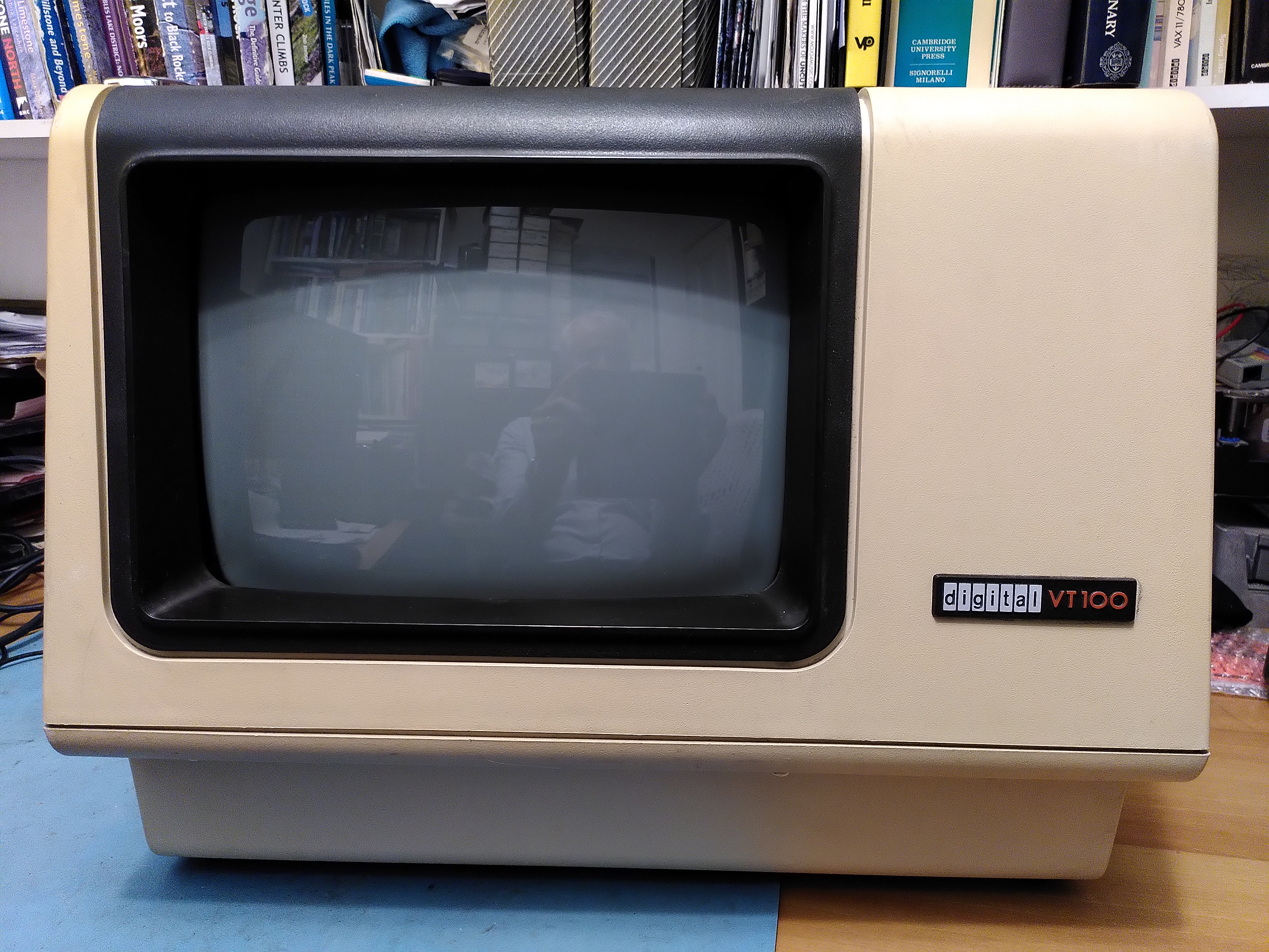
| Model | VT100 |
| Model Number | VT100-AB |
| Serial Number | AB73340 |
| Release Date | 1978 |
| Cost New | ? |
| Acquired | 2022-08-22 |
| Configuration | No keyboard, no options, spare access cover. Elston monitor |
| Status | External video works Flyback has failed (monitor board status consequently unknown) Diodes on basic video board for the -23V supply get very hot |
| Printset | Basic video board: March 1980 version applies Monitor board: See Micro-Term MIME 1 manual |
The VT100 is the classic serial video terminal. It implemented a standard for escape codes to control the terminal, and VT100 emulation survives to this day. It was used to communicate with any machine that had a RS-232 serial interface, and was used extensively with the VAX line of computers.
It had an 80-character by 24 line display, but it could also do 132-character width, double-height, double-width etc. It had some basic box-drawing characters to allow some very basic graphics to be drawn. It was built around the Intel 8080 processor, which executes the firmware that implements the control of the terminal.
The VT100 had several variants like the VT101, VT102 and VT125.
This particular terminal was not in good condition when I received it. It had a RAM fault, the communication with the keyboard did not work, there was an NVR checksum error, then I could not get a sensible image on the external video output and I also noticed that the Video Shift Register was getting very hot as were the diodes on the -23V PSU output.
I made a few repairs, as listed in the table below. The NVR checksum error was just that over time the ER1400 chip had lost its data and I just needed to save it again. I only found out after unnecessarily replacing the ER1400, but I socketed it so the original chip is still installed.
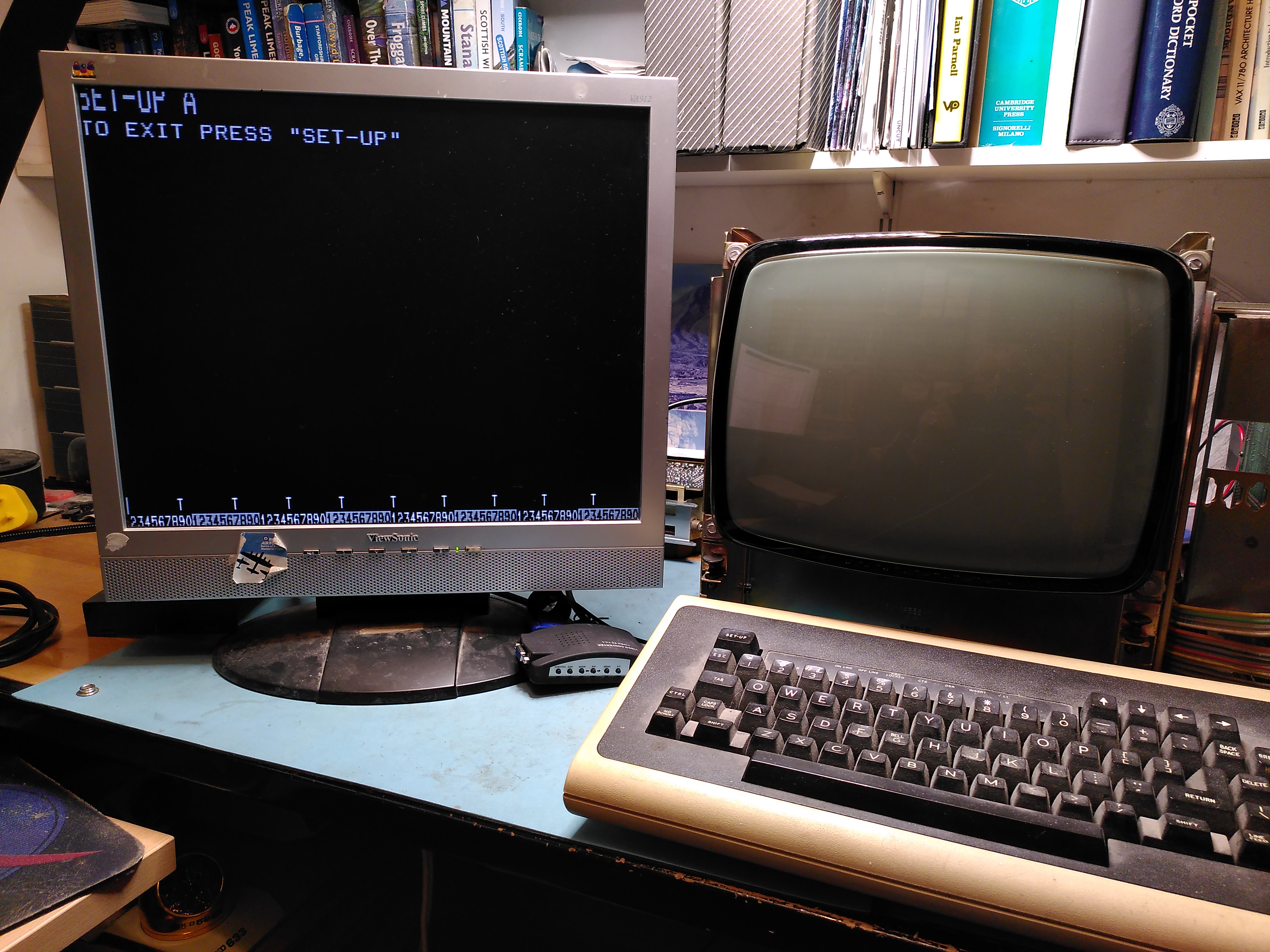
It is now able to work with the external video output. The monitor does not work because the flyback transformer (part number 16-16463-00) has failed.
Restoration History
| Date | Details |
|---|---|
| 2022-09-18 | Added missing screw for heatsink on the 7812 (Z2) regulator in the power supply. See VT100 Ram Fault. |
| 2022‑09‑19 | Recapped the video monitor board, apart from the non-polarised one. See VT100 Ram Fault. |
| 2023-10-01 | Replaced RAM chip E51. However because of an error I actually moved E50 to E51 and put a new chip in at E50. See VT100 Ram Fault. |
| 2023-11-19 | Replaced UART on the basic video board for communicating with the keyboard. See VT100 Keyboard Constant Clicking Fault. |
| 2023-12-06 | Replaced fuse F401 on monitor board. |
| 2024-03-11 | Replaced E10 (a shift register) that is getting too hot, but it still gets too hot. |
| 2024-04-09 | Replaced the DC012 (E5) video control chip, using a socket. Restored external video. See VT100 External Video Fixed. |
| 2024-04-28 | Fixed dry joint on C47 on the Basic Video board. |
| 2026-03-28 | Replaced Q414 and CR406 with NOS 2SB411 germanium transistors, repaired wires to tube neck connector. |
| 2026-03-30 | Confirmation that the flyback has failed. See VT100 Video Display – Failed Flyback Transformer. |
| 2026-04-04 | Socketed the original ER 1400 NVR chip (E24) when suspecting it was faulty and temporarily replacing it. |
Repair Reference Information
This section provides some notes that may be useful to anyone wanting to repair a VT100. The Technical Manual is invaluable and is available on BitSavers.
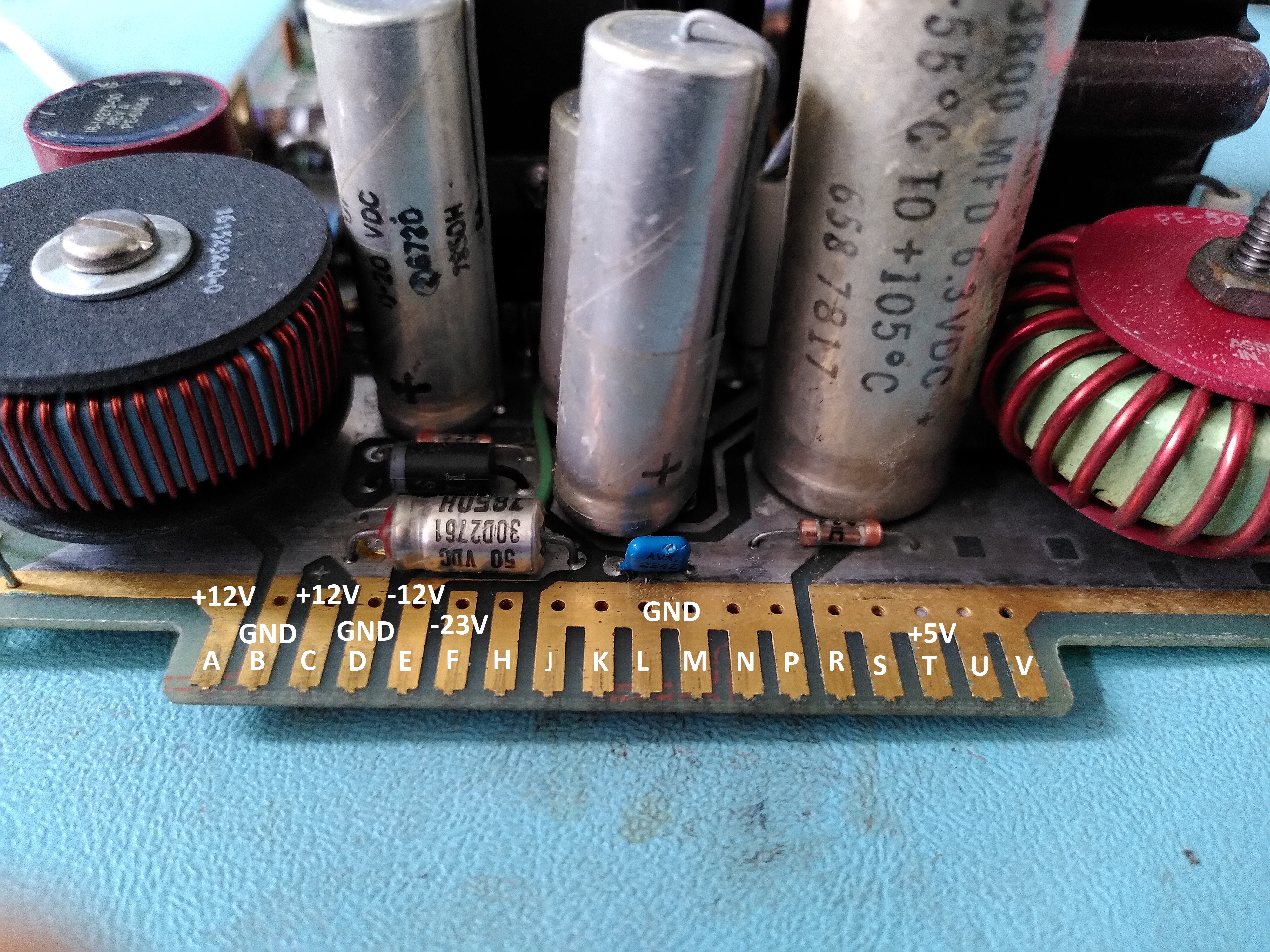
Power Supply
The pinout for the power supply connector is shown below:
Basic Video Board
There is a fantastic annotated disassembly of the firmware here.
The table below describes how to set up a logic analyser to capture various aspects of the operation of the board. It is worth noting that many of the signals, in particular the address and data bus, are available easily on the big connector marked J1.
| Intent | Trigger |
|---|---|
| RAM read | Trigger on the rising edge of BV6 MEM RD. Need to wait for the 5th access to avoid the RAM test. |
| RAM write | Trigger on the falling edge of BV6 MEM WR. |
| Execution of a ROM address | As for RAM read but trigger on the second occurrence to avoid the ROM checksum. |
| Keyboard write | Connect to XD0-XD7 (TBR1-TBR8) on the UART and trigger on the rising edge of LD XD (TBRL). |
| Reads during DMA | Trigger on the rising edge of BV4 CHAR CLK H, and BV4 DMA ENA L must be low. Address filter should be 2XXX. |
| Scan count on DC012 | Trigger on the negative edge of HORIZ BLANK H. |
| Commands to DC012 | Trigger on rising edge of VID WR2 L. |
The serial communication with the keyboard is 7866 bits/sec, 8 stop bits, 1 stop bit, no parity. The data is in MSB order. The polarity appears to be the opposite of what you might expect.
Other
A common problem with the enclosure is that the grommets that hold the case together break. A useful source of these grommets in the USA is listed in the following forum post.
