Now that I have acquired a DSO (a Rigol DS1054Z), I have been doing more work to understand the failure of the H7270 PSU on my VAXmate that I first blogged about here. I still don’t fully understand the problem, but I now have an improved insight into what is going on and a possible explanation. The schematics I refer to in this post are:
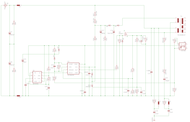
H7270 Primary Side
Below is a trace from the oscilloscope during startup of the PSU. What you can’t see here is that Ch1 was steady at about 5V for 15ms before the oscillations start, and this corresponds to a point when voltage on Vcc to the UC3842 has finished ramping up.
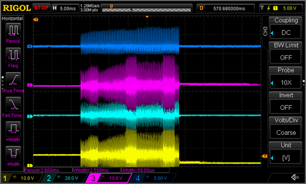
CH1: Vcc for NE555 and Vref for UC3842 CH2: Base of switching transistor Q1 CH3: Gate of SCR D19 which shuts down on overcurrent CH4: Current sense resistor (R13)
It looks like after the 15ms that the UC3842 starts to switch the transistor. This also corresponds to when Vcc on the NE555 starts to oscillate. The transistor switches for about 25ms and then stops. I have not been able to work out why it stops. I had been thinking that it was because the SCR (D19) was being triggered, but Ch3 of the trace shows it getting pretty much the same signal throughout the period and there is no change at the time the PSU stops, so I am not sure if the SCR is being triggered or not. After all, the voltage across the current sense resistor is not varying much either.
I was puzzled though as to why Vcc to the NE555 starts to oscillate a lot. My guess was that it is because the output from the transformer has not settled yet. I don’t understand why it is quite so spiky though, I imagined a capacitor would smooth it, but I am not sure. I found one capacitor that looks like it is supposed to smooth Vcc (C11). I took it out of circuit to measure it, nominally it should be 220nF, it measured 335nF initially, but as I left it connected to the meter it dropped in about 5 minutes to 300nF, and kept dropping slowly over time.
I decided I needed to improve my schematic. To help me detect the connections correctly removed the transformer (T1). This is it here:

H7270 Transformer
While I had the transformer out of circuit, I decided to carry out a ringing test on it. Unfortunately, this is where I think I may have found the problem. Four of the windings ring correctly, but one of the windings does not ring, it is the one shown as P1 in the schematic, and it is the two pins on the left in the picture above. However, the Technical Description says that one of the primary windings is operated in flyback mode to provide bias voltage for the pulse width modulator. I don’t know if that has any implication for the ringing test though. Here is the scope trace
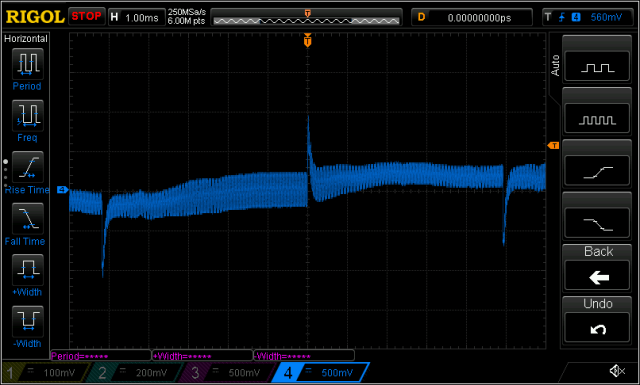
H7270 Transformer P1 Ringing Test
Another curiosity is that the pin on the right in the picture does not seem to be connected to any other pin on the transformer. I suppose this might mean that a wire has broken somewhere perhaps. I don’t know if transformers can fail with a nasty smell and no outward signs of damage, but I fear it has failed, and that it will be very hard to replace. I am also concerned that if I could replace it some other fault would damage the replacement too.

Shorted turns can certainly cause a burning smell. It should be relatively easy to have the transformer rewound if that proves necessary.