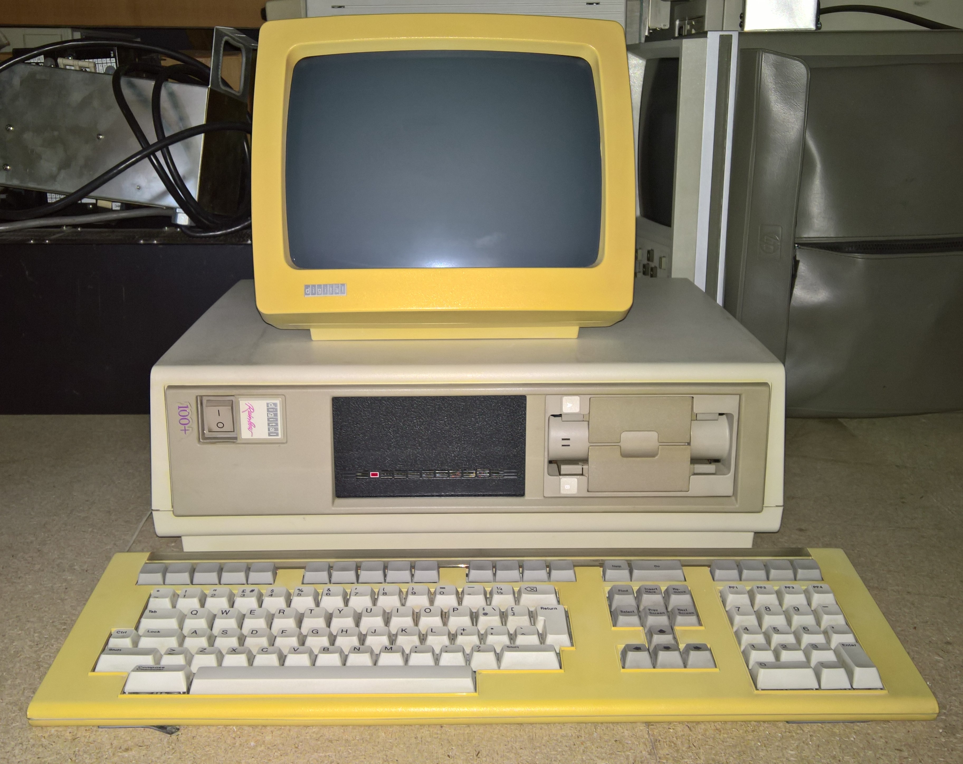
A couple of days ago, I received a request to format some RX50s in one of my Rainbow machines. So, I got this one out to check that it still works. I was happy that it just powered up fine. I went off to search for some RX50 diskettes to check the floppy disk drive with. When I came back the machine was silent. It had powered itself off. There was a vague burning smell and the circuit breaker on the back had popped.
Not knowing if there was perhaps a short in the machine or a problem in the power supply, I disconnected the fans, the floppy disk drive, the hard disk drive and, probably foolishly, I applied power again to see if the machine would work. At this point there was a bang and a flash in the power supply.
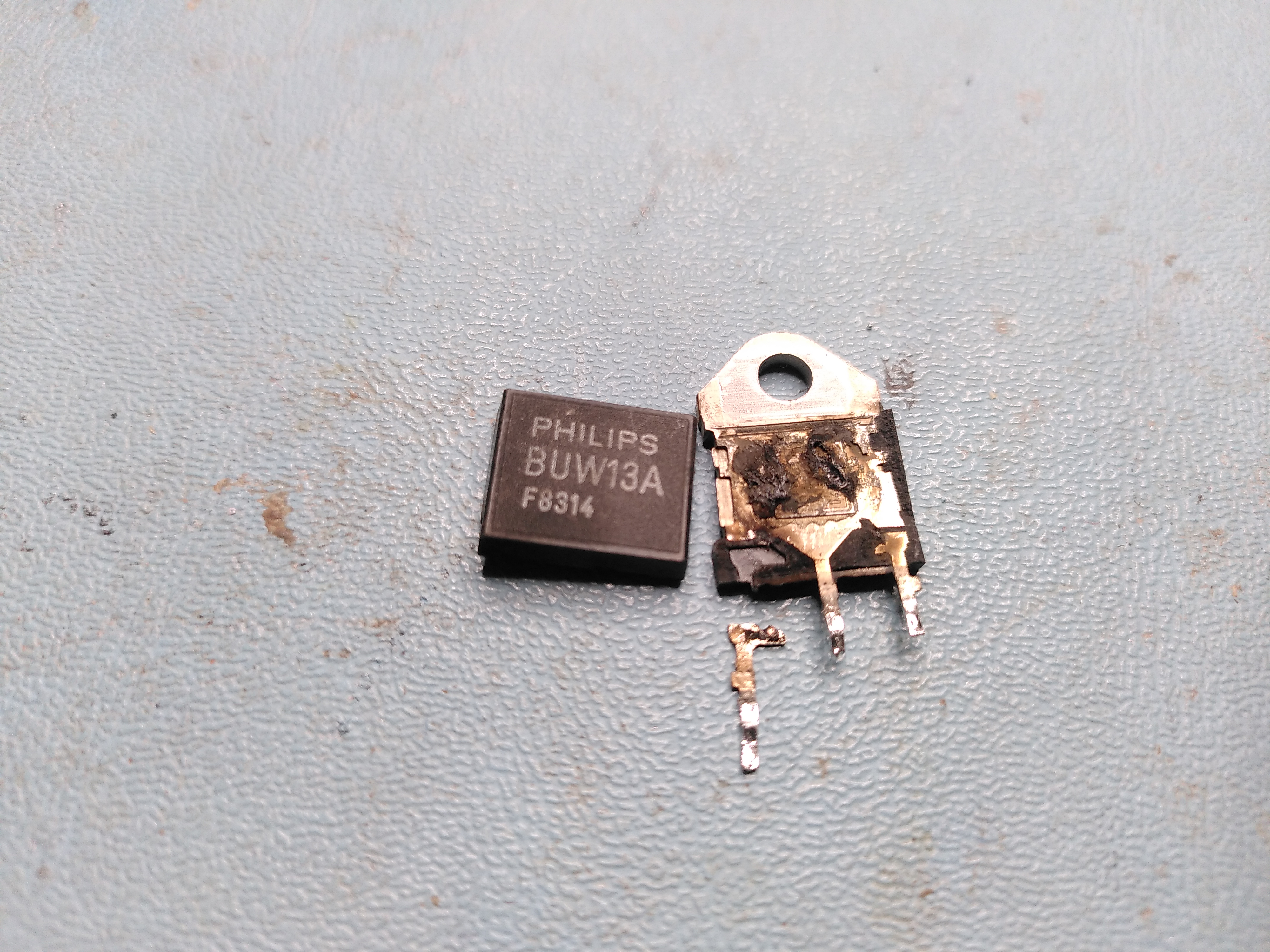
On opening up the H7842 power supply I found that one of the transistors had completely disintegrated. It looks to be the main switching transistor.
Given that before the transistor blew up there had clearly been another failure somewhere else, I tried to find the original failure. There were no obviously damaged parts, so I just probed around near the transistor for any parts that were open circuit or short circuit. I found a diode connected to the base of the transistor that appeared to be short circuit. So, I decided to lift one end to check it. As I de-soldered one of the leads, the diode broke in two. So clearly the diode was either damaged by the failure of the transistor, or it was the cause of the failure. This is the diode:
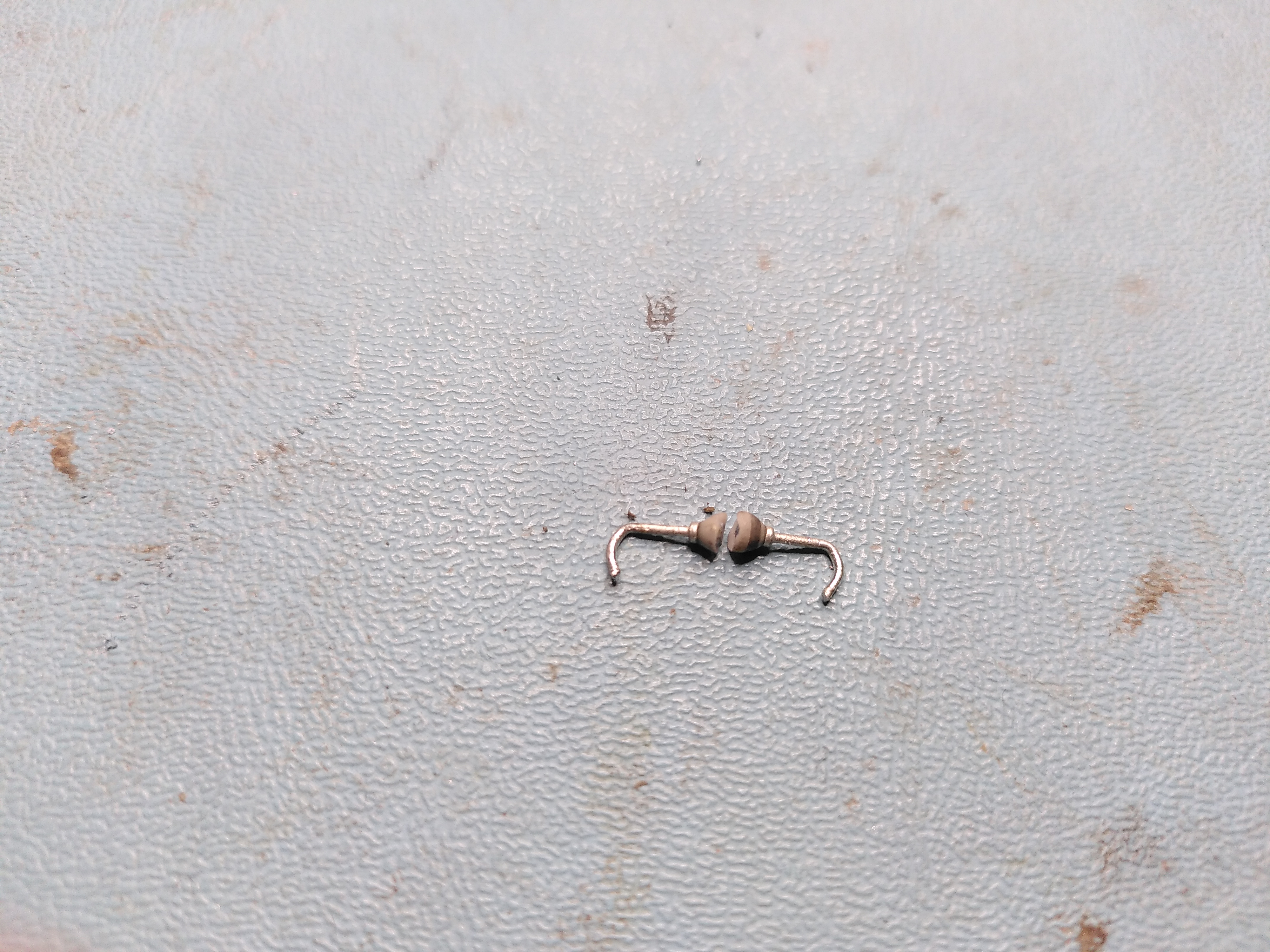
Tony Duell has reverse engineered the schematic for this power supply here. The transistor that failed is the one on sheet 2 labelled BUV48A and the failed diode is the one connecting the base of the transistor to the transformer and in parallel with a 2.7R resistor. I obtained a replacement BUV48A. I couldn’t identify the diode, the markings looked like they said “D610” but I couldn’t be sure, so after advice from the cctalk list, I replaced the diode with a UF4007. I also discovered that the 7812 regulator (sheet 1 of the schematic) had failed, so I replaced that too.
On further advice, I tested the control board in isolation by using a bench power supply to put 15V into the 7812 regulator mentioned above. On a working PSU you can see the PWM (Control Module Sheet 2 on the schematic) producing a signal that turns the chopper transistor on and off and the current draw from the PSU is about 87mA. However, the PWM was not producing a signal on Output A and the current draw on the bench PSU was about 140mA. Furthermore the 5.1V reference voltage was actually 9.75V. So the PWM was faulty and I replaced this with a UC3527AN.
Despite replacing the PWM, it still did not operate. I discovered that the Shutdown pin on it was being asserted. I traced this to an LM339 comparator (E3 on Control Module Sheet 1 of the schematic). The output was incorrect given the inputs.
I replaced the comparator. However the E3c output is high and so it is shutting down the PSU. Tony’s schematic seems to have some errors on it in this area. Reverse engineering the circuit it looks to me like E3c has the ISense -12V- and ISense -12V+ as inputs, so the comparator marked E3d on Tony’s schematic is actually E3c.
So, the problem now is that there appears to be an overcurrent in the -12V circuit. This is being detected even when I use a bench PSU to supply the Vstart signal only by applying 15V to the input of the 7812 regulator on PSU Sheet 1 (page 2 of the PDF).

I would look for a short on the low voltage rails on the secondary side of the power supply. DEC frequently used identical diodes in several positions within power supplies. Any Silicon diode rated at 1.0A and say PIV=200 would be more than adequate. On second thoughts you should scrap the Rainbow and give it all to me.
see: http://www.bitsavers.org/pdf/dec/rainbow/duell_schematics/psu.pdf
You’ll have to do some circuit tracing, but it has component values (believed to be accurate).
Pingback: The Continuing H7842 Saga | Rob's Old Computers