I have been working on the H7826 power supply that came in the TURBOchannel Extender of my DECstation 5000/240. Normally, after a visual inspection, I will just apply power to see if a PSU works. This one, though, was not in a very good state, with a lot of dirt and corrosion, and bits of heat sink all over the board. You can see more details in my earlier post.
So, the first step was to clean it up and replace many of the electrolytic capacitors that are apparently known to fail. Most of the capacitors I removed were in the output area, although I did remove a couple of small electrolytics near the two big input smoothing capacitors. After removing the capacitors in the output area and cleaning it up it looked like this:


I did not find evidence of leakage, but the dark area under one of the capacitors is a bit suspicious. I tested the continuity around the dark area and it seems fine. I then replaced the capacitors and cleaned the corroded heat sinks as best I could. The results are in the pictures below:


So then it was time to see if the PSU works. I reassembled it, making sure the fans were attached, as well as the status LED. I applied power and….. nothing. I was disappointed, but not surprised.
I did some probing around to see at which point the PSU is failing. I found the voltage across the big smoothing capacitors was a healthy 330VDC or so, so they are fine (they were not fine on the H7878 in the DECstation itself). I then checked the primary side of the transformer and I could see a signal. However, when I checked the secondary side of the transformer there was no signal at all.
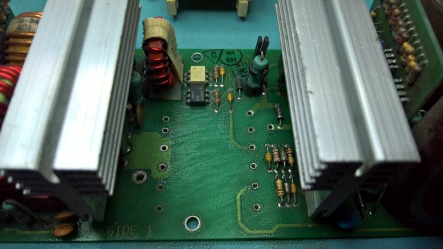
This could be a problem with the transformer itself, or something else after the transformer. It was impossible to check without removing parts, so I started by removing the transformer. Here is the board without the transformer (primary side on the right):
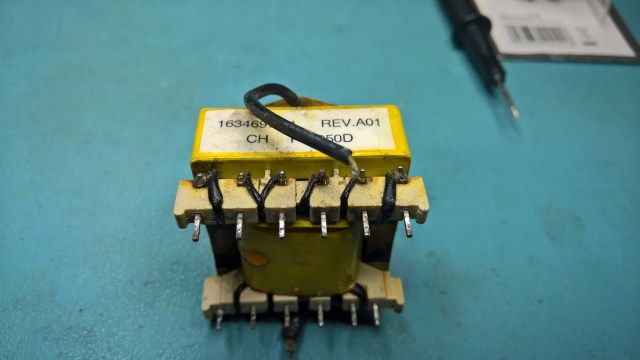
In the two pictures that follow I arbitrarily numbered the pins 1 to 6 from left to right. This is the primary side, where the windings are 1-6, 2-3 and 3-4:
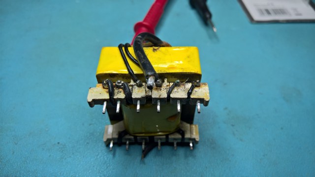
This is the secondary side, where the windings are 1-2, 3-4 and 5-6:
While I was at it I got out a ringing tester that I made a while ago (thanks to a member of the classiccmp mailing list) to make sure that the transformer is working and does not have any shorted windings.
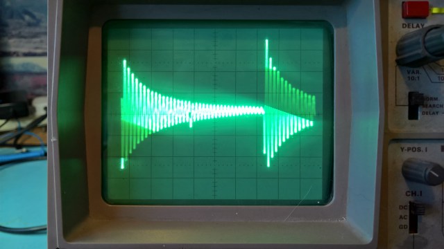
This is the result of the ringing test on pins 1-6 of the primary side:
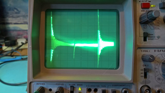
On the secondary side pins 1-2 and 5-6 gave this result:
The other windings all looked like this:
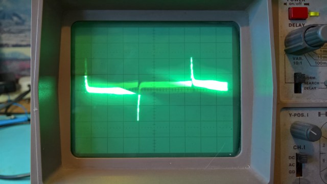
I am told the latter result may be because there are insufficient turns on the windings being tested, and that these results show that the transformer is working and there are no shorted windings. That is a huge relief because I suspect that the transformer would be very hard to replace.
The next thing to check was the output rectifier. In circuit, one of the diode networks (an MBR 3045) appeared to show some shorts. That meant I had to remove them, to test them out of circuit. The problem here is that the rectifiers are screwed into a large heat sink and the parts around the heat sink make it impossible to reach the screws. This meant that I had to remove the whole heat sink. To make matters worse, the heat sink is fixed to the board by two pegs. I could not see how the heat sink was connected to the pegs
To do this I first had to de-solder the three diode network parts and the temperature sensor. Once I had done that I tried gently levering the heat sink off the pegs, in the hope that the heat sink was just held on the pegs by friction. Thankfully this turned out to be the case. I used a little bit of WD40 to help the process, letting it soak in first, and I soon had the heat sink and the 4 components attached to it out of the board. The pictures below show the pegs and the heat sink:


I used a Peak DCA55 tester to check the diode network parts and they seem to be working fine, so that is not the cause of the transformer not showing any outputs. When probing the holes in the board, the ones for the rectifier network nearest the output still appeared all to be shorted together, but I traced that to two low-value resistors, so that is not the problem.
So I am still stuck not knowing why there seems to be no signal on the output windings of the transformer.
