| Make | Digital Equipment Corporation |
| Model | Rainbow 100 |
| Model Number | PC100-A |
| Serial Number | WF54026 |
| Processor | Intel 8088 and Zilog Z80 |
| Bus | |
| Release Date | 1982 |
| Cost New | ? |
| Acquired | 2024-11-16 |
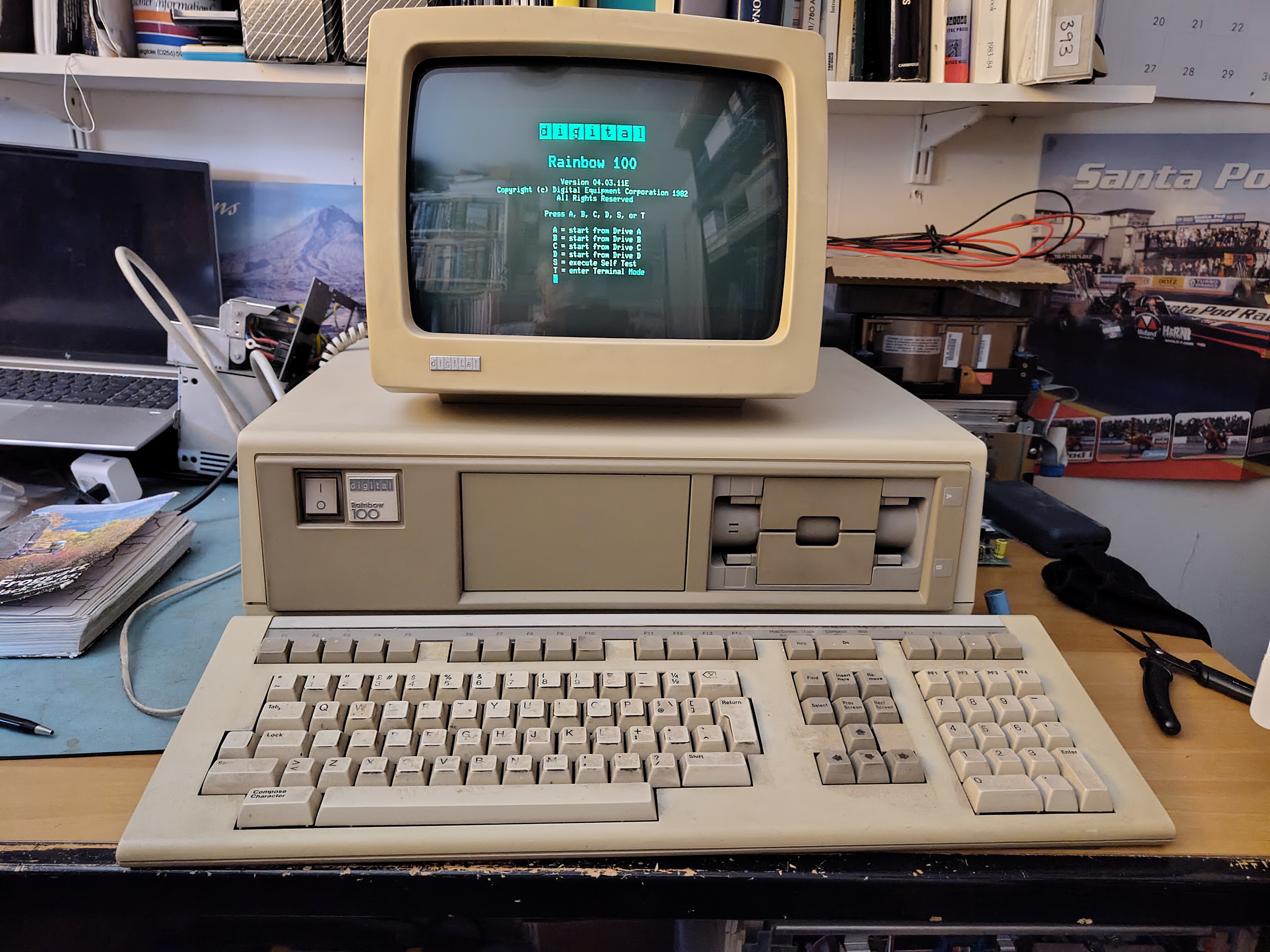
| Configuration (as collected) | Floor stand VR201. Green (bad cataracts) 64KB memory LK201 keyboard RX50 floppy disk drive LA50 printer |
| Current Configuration | Unchanged |
| Status | Operational |
| Documentation | https://bitsavers.org/pdf/dec/rainbow/ |
The Rainbow was an early attempt by DEC to enter the personal computer market. DEC’s failure in this market ultimately led to DEC’s demise. The Rainbow is based on the Z-80 and Intel 8088 CPUs, so it can run CP/M or MS-DOS.
I was given this particular machine by someone in Ramsbottom, Lancashire. It came from the estate of a radio amateur in the Bury area, now a “Silent Key”. It came with a monitor, keyboard, an LA50 printer, various floppy disks and a set of manuals. This being the most basic A model, does not support a hard disk.
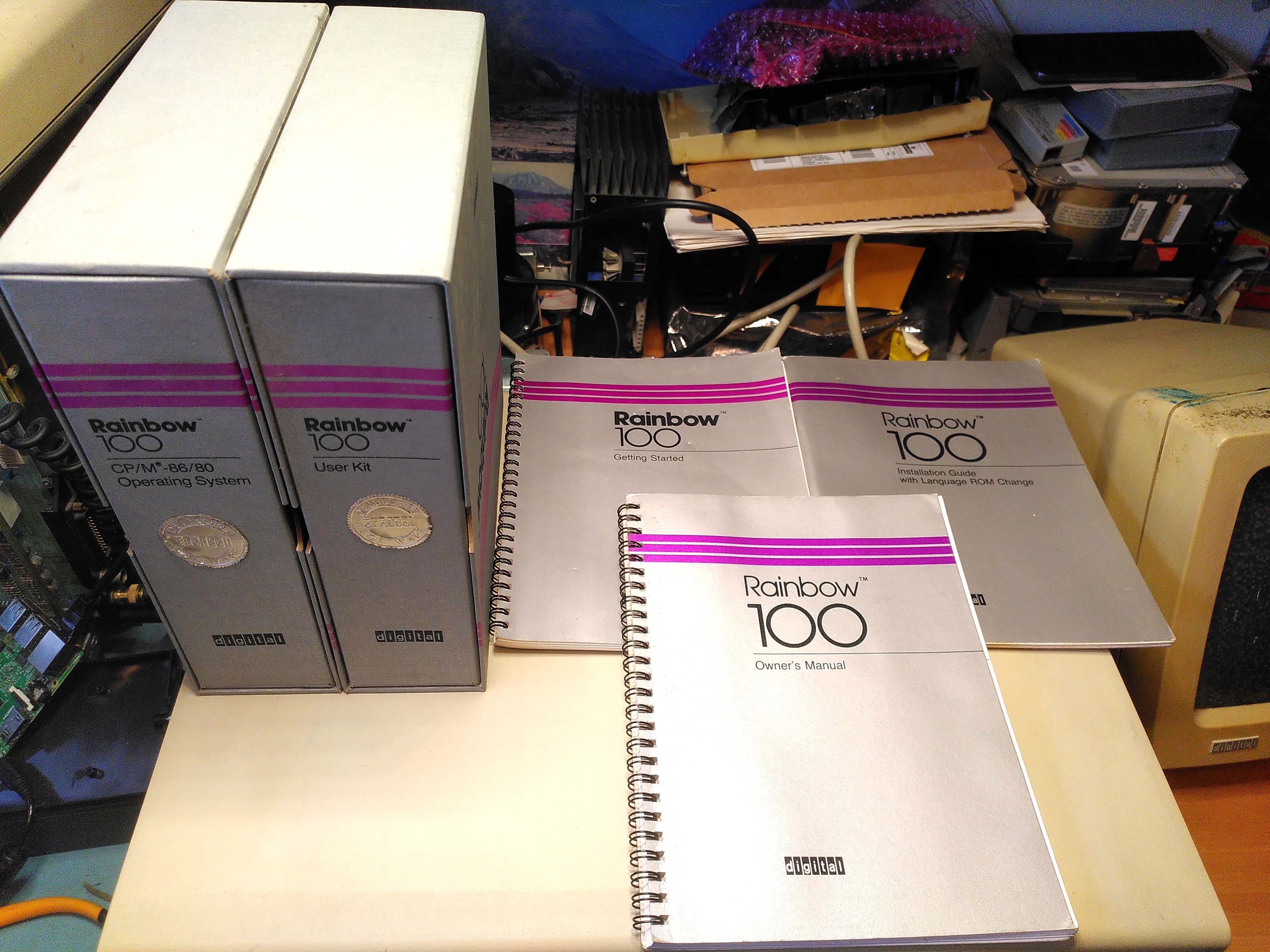
It came with the following manuals and software:
- AA-N575A-TV Rainbow 100 Getting Started
- EK-P100E-OM-001 Rainbow 100 Owner’s Manual
- EK-P10BR-IN-001 Rainbow 100 Installation Guide with Language ROM Change
- AA-P300A-TV Rainbow 100 User’s Guide
- EK-0LA50-UG-001 Installing and Using the LA50 Printer
- EK-0LA50-RM-002 LA50 Printer Programmer Reference Manual
- Rainbow 100 User Kit box, containing:
- EK-DECRB-IN-001 Floor Stand Installation Guide
- AA-N649A-TV Rainbow 100 Read Me First with Language ROM Change
- AA-P300A-TV Rainbow 100 User’s Guide
- Rainbow 100 CP/M-86-80 Operating System box, containing:
- AA-N575A-TV Rainbow 100 Getting Started
- Shipping protectors for RX50
- Software box containing:
- BL-T309B-BV RAINBOW 100 DIAG DSK RX50
- BL-N651A-BV SYSTEM OVERVIEW BIN RX50
- BL-N648A-BV CP/M-86/80 V1.0 BIN RX50
- Unofficial CP/M-86/80 Distribution Backup
- Software box containing:
- BG-P876B-BV Language ROM
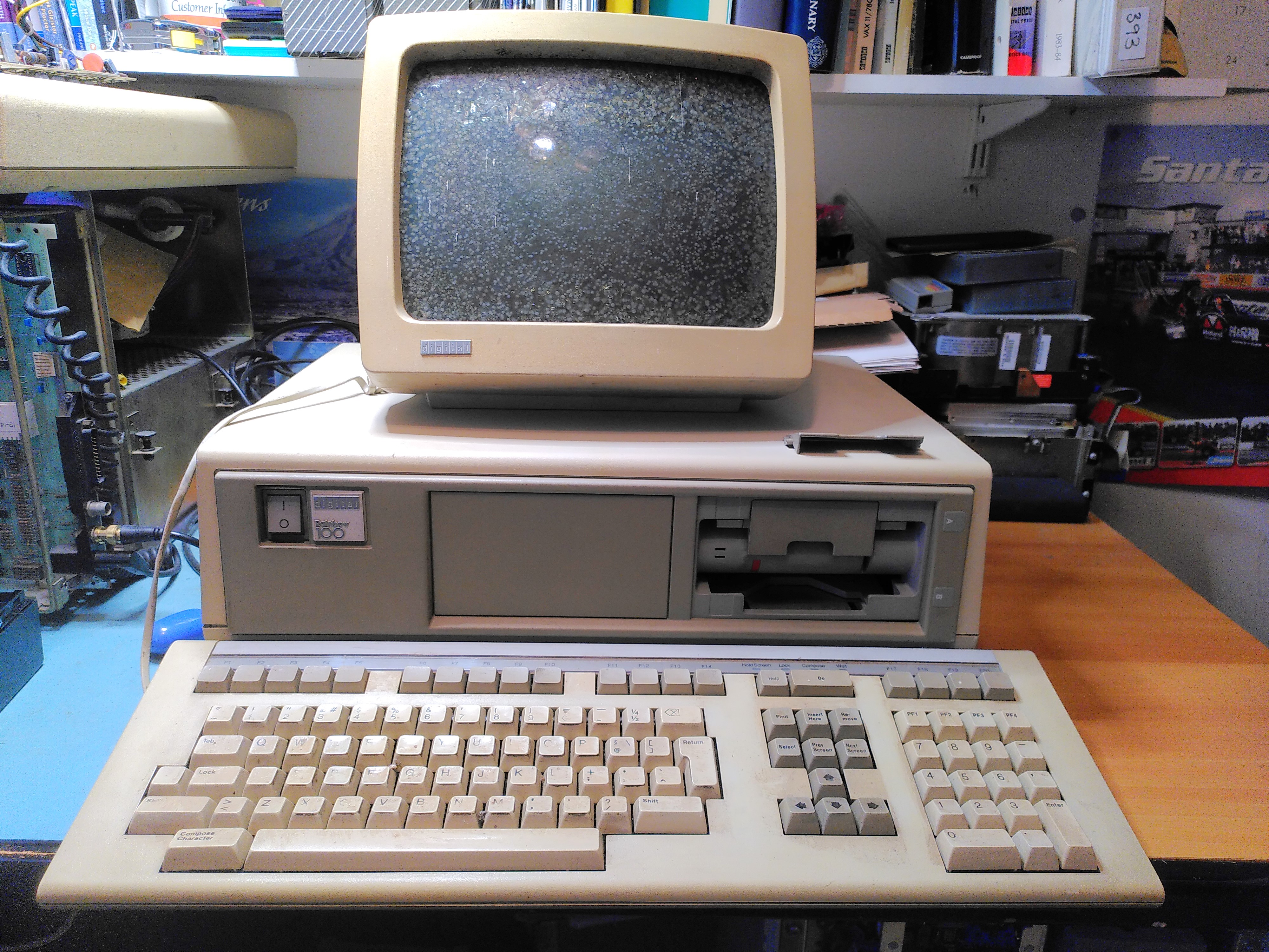
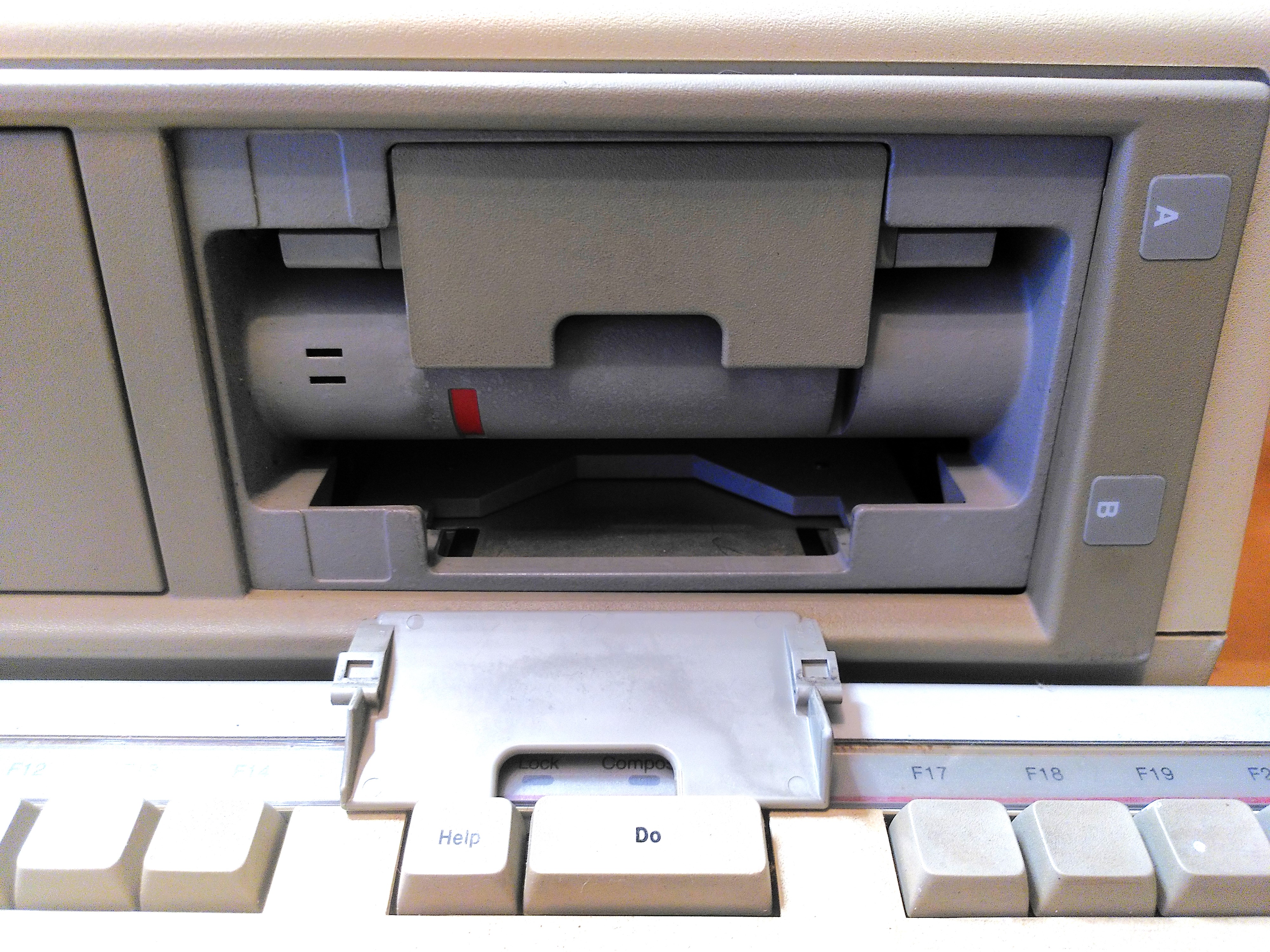
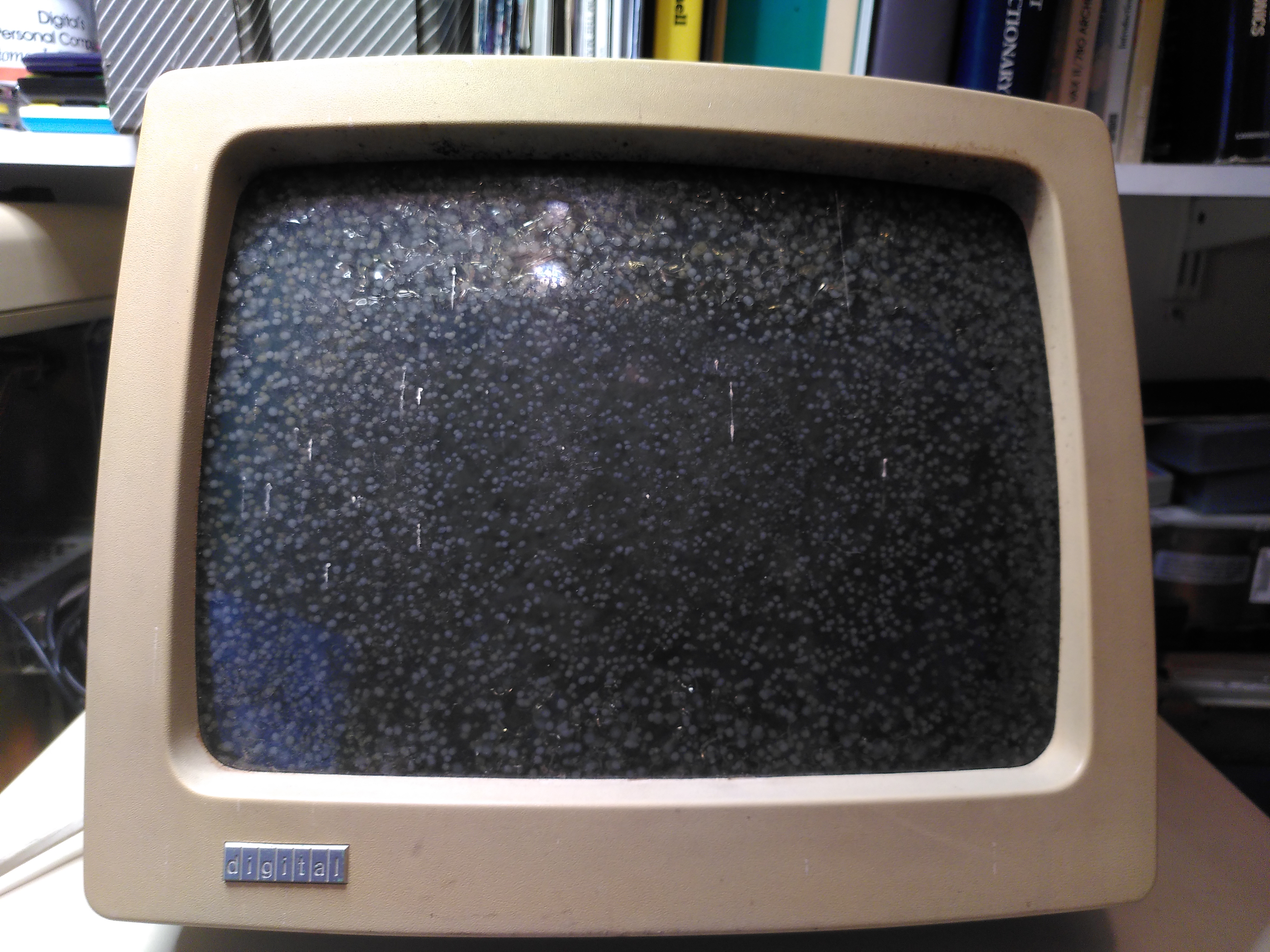
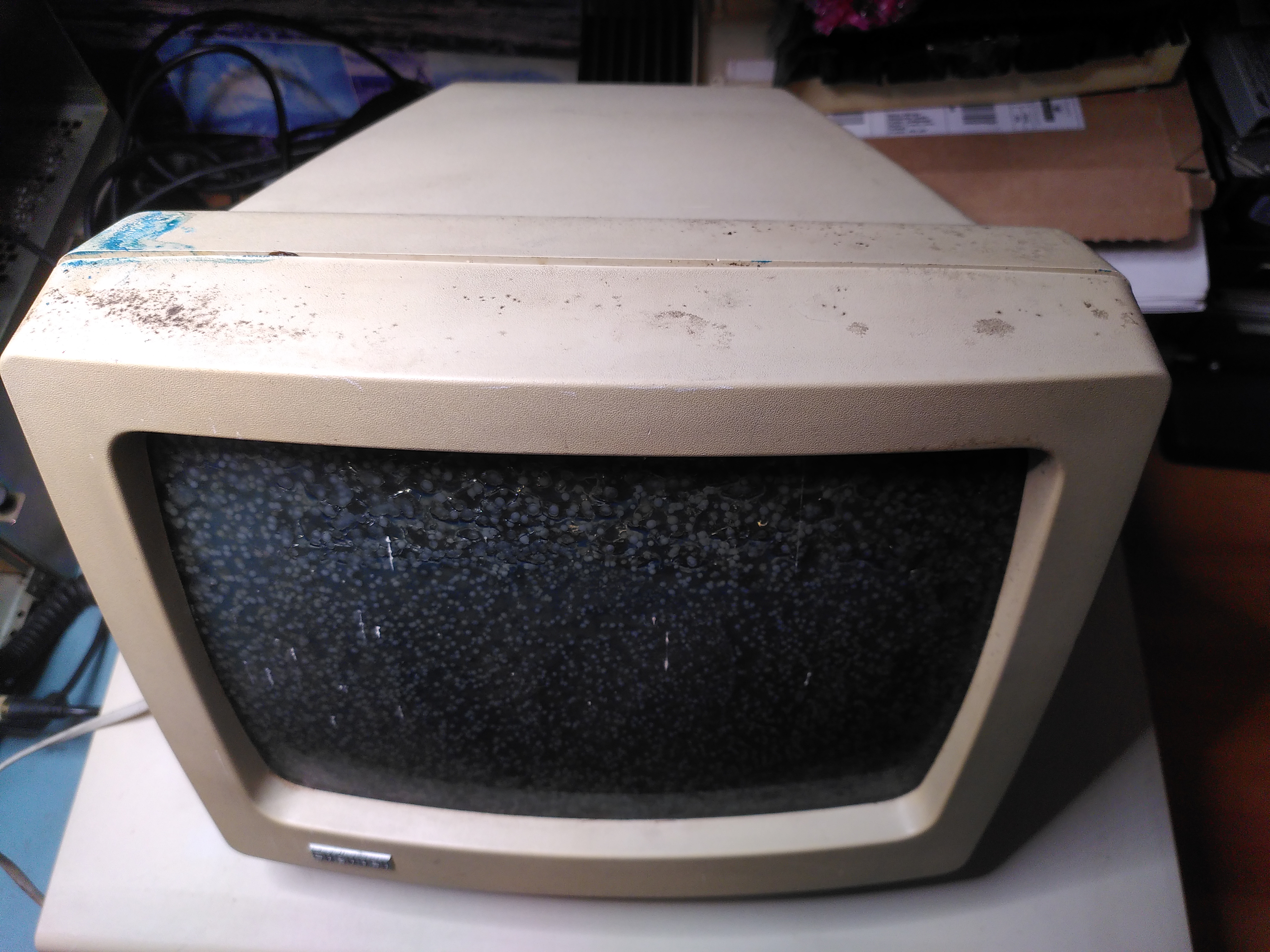
Sadly the VR201 monitor was suffering badly from screen “cataracts”. While loading the machine into my car one of the floppy disk doors came adrift. When I got it home I found that the pins holding it seem to be missing and likely got lost during the loading process. While there seemed to be some paint marks on the monitor and the keyboard cable, the inside of the machine itself was very clean.
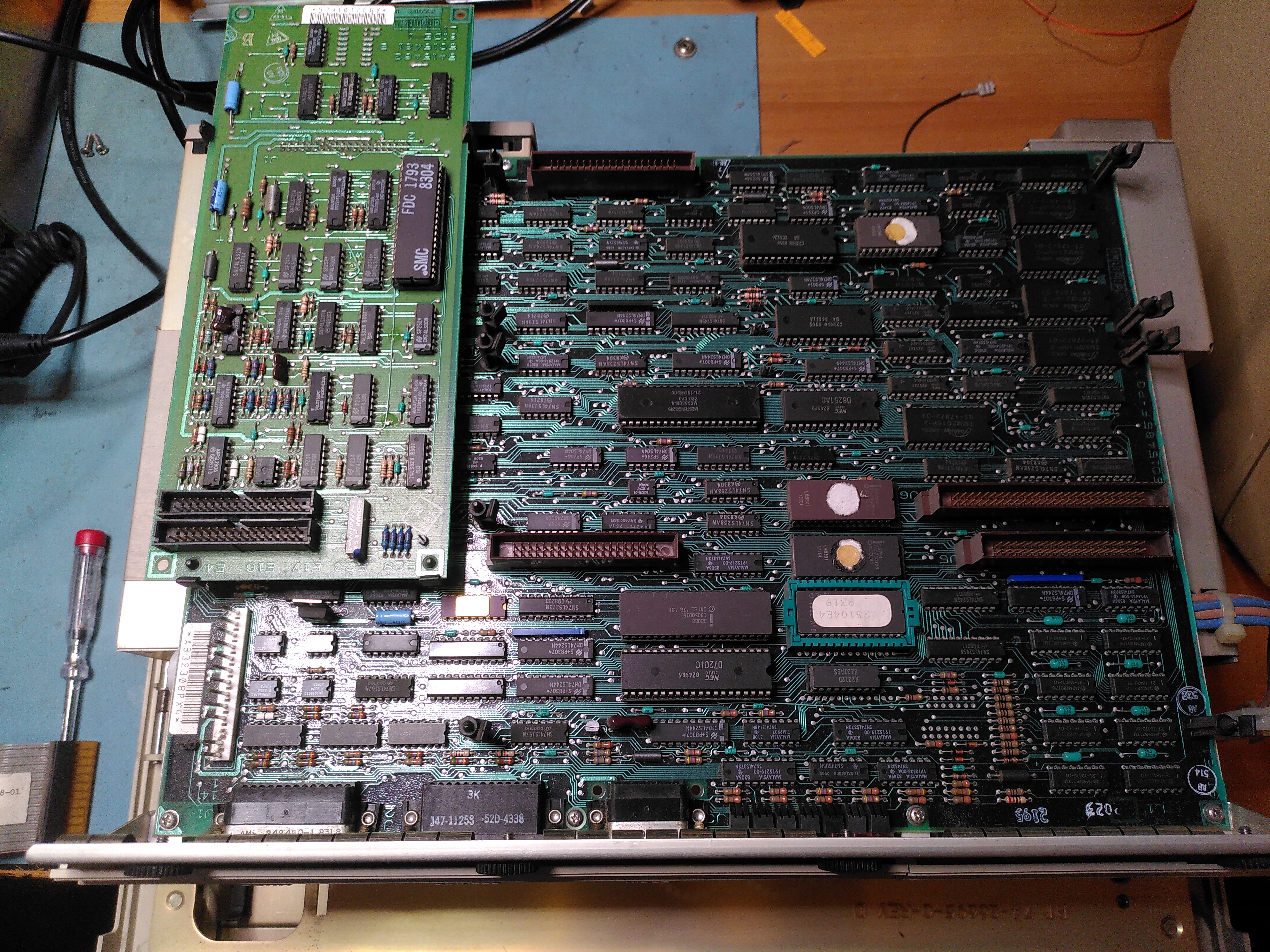
The machine powered on, flashing the keyboard and RX50 lights and turning the fans. The monitor came on but didnot display an image. The diagnostic LEDs on the back displayed 1110110. The online Owner’s Manual does not describe this code, but the paper copy that came with the machine indicated that this was a Video RAM fault.

I have since the restored the machine as detailed in the following blog post.
Restoration History
| Date | Details |
|---|---|
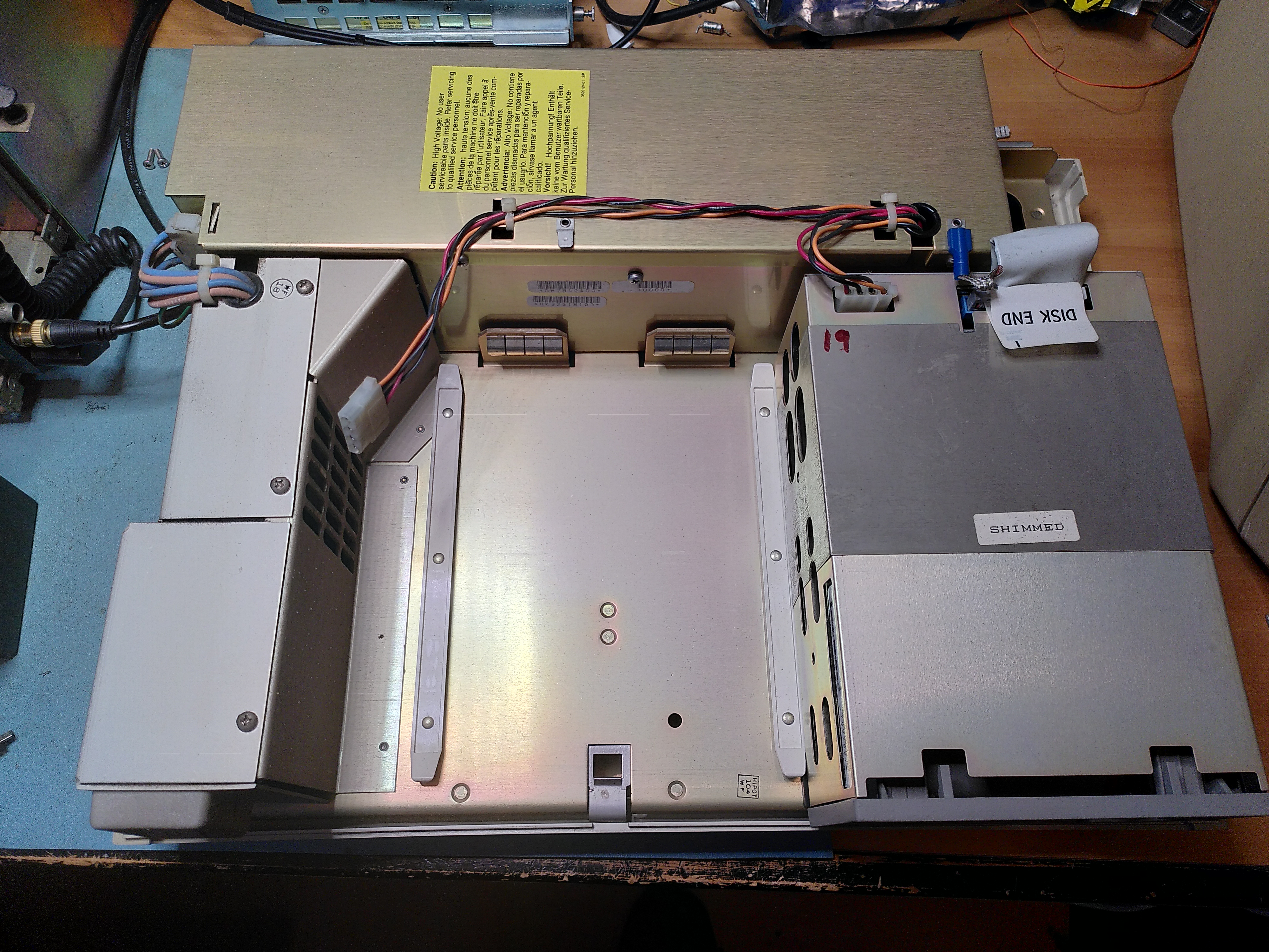
| 2024-11-16 | Visually examined power supply, the electrolytic capacitors showed no leaks or bulges. Tried to fix floppy door but found pins missing. |
| 2024-11-24 | Replaced E122 (Video RAM), now diagnostic LEDs indicate Main Board Video error. |
| 2024-11-28 | Fixed RX50 door with a new pin. |
| 2024-12-01 | Replaced QIKEJECT socket for E89 with normal socket. |
| 2025-03-08 | H7842 PSU failed, power entry module shorted, replaced PSU with a spare. |
| 2025-03-16 | Replaced E100 (line buffer static RAM) and the board started working. |
| 2025-04-20 | Replaced power entry module on the original H7842A Power Supply and reinstalled it. |
| 2025-07-25 | Fixed cataracts on VR201. |
| 2025-07-28 | Replaced some capacitors in the VR201. |
Repair Reference Information
ROMs
I have a partially annotated disassembled ROM here. The disassembly is incomplete and there is some embedded data in places, I don’t know if I have identified them all, so the disassembly may be incorrect in a few places.
ROM 0: 23-176E4-00, part E89. Disassembly
Logic Analyser Setup
To capture addresses and data from the 8088 use a multiplex mode on the logic analyser. To get the address trigger on the negative edge of ALE. This is a good point to capture the IO/M signal on pin 28 as well. Complete the cycle to get the data from the bus by triggering on the positive edge of DEN, this is the point to capture the RD signal on pin 32 to distinguish reads and writes.
Diagnostic LEDs
| Label | D11 | D10 | D9 | D6 | D5 | D4 | D3 |
| Bus bit | 5 | 7 | 6 | 4 |
Memory Map
The tables below lists the locations that I have identified in the ROM code and their possible purpose:
| Address | Description |
|---|---|
| 0x0503 | Video controller is OK if it matches the mask 0x2 |
| 0x0505 0x0506 | Possibly pointer to a diagnostic message displayed on screen. It is the location in a table of pointers to the actual string. |
| 0x252C | Stores diagnostic LED values to be displayed |
| 0x2530 | DC012 Vertical interrupt counter. During self-test a temporary interrupt routine at 0x11E1 counts the number of interrupts. |
| 0x2532 | Printer status (MPSC). Bits are (starting at LSB): 0: The transmit buffer is empty 1: A character was received 2: Some kind of transmit error relating to SDLC 3: A character was received but there was an error |
| 0x2533 | Communications status (MPSC). Bits are (starting at LSB): 0: The transmit buffer is empty 1: A character was received 2: Some kind of transmit error relating to SDLC 3: A character was received but there was an error |
| 0x2534 0x2535 | Some kind of status byte for the video controller check. If it matches any bits out of the value 0x78 then the video controller is OK. Bits are (starting at LSB): 0: Keyboard TxEMPTY is set 1: Ready to transmit to the Communications port (MPSC) 2: Ready to transmit to the Printer port (MPSC) 3: 4: Vertical interrupts are being delivered 5: Something about finding FFFF in the ROM 7: Possibly used as a canary to spot RAM errors Upper byte Seems to count outstanding characters to transmitted or received (keyboard and MPSC channels). It is cleared with word operations on 0x2534. |
For the keyboard control block
| Address | Description |
|---|---|
| 0x2536 | Possibly a count of the number of times to send the keyboard transmit buffer character. |
| 0x2537 | Transmit buffer. |
| 0x253A | The last status read from the keyboard status register. |
| 0x253B | Read buffer |
For the MPSC Communications Port Control Block
| Address | Description |
|---|---|
| 0x253C 0x253D | DC012 vertical interrupt counter |
| 0x253E | Contents of RR0 from MPSC chip |
| 0x253F | Contents of RR1 from MPSC chip |
| 0x2540 | Read buffer |
For the MPSC Printer Port Control Block
| Address | Description |
|---|---|
| 0x2541 0x2542 | DC012 vertical interrupt counter |
| 0x2543 | Contents of RR0 from MPSC chip |
| 0x2544 | Contents of RR1 from MPSC chip |
| 0x2545 | Read buffer |
