
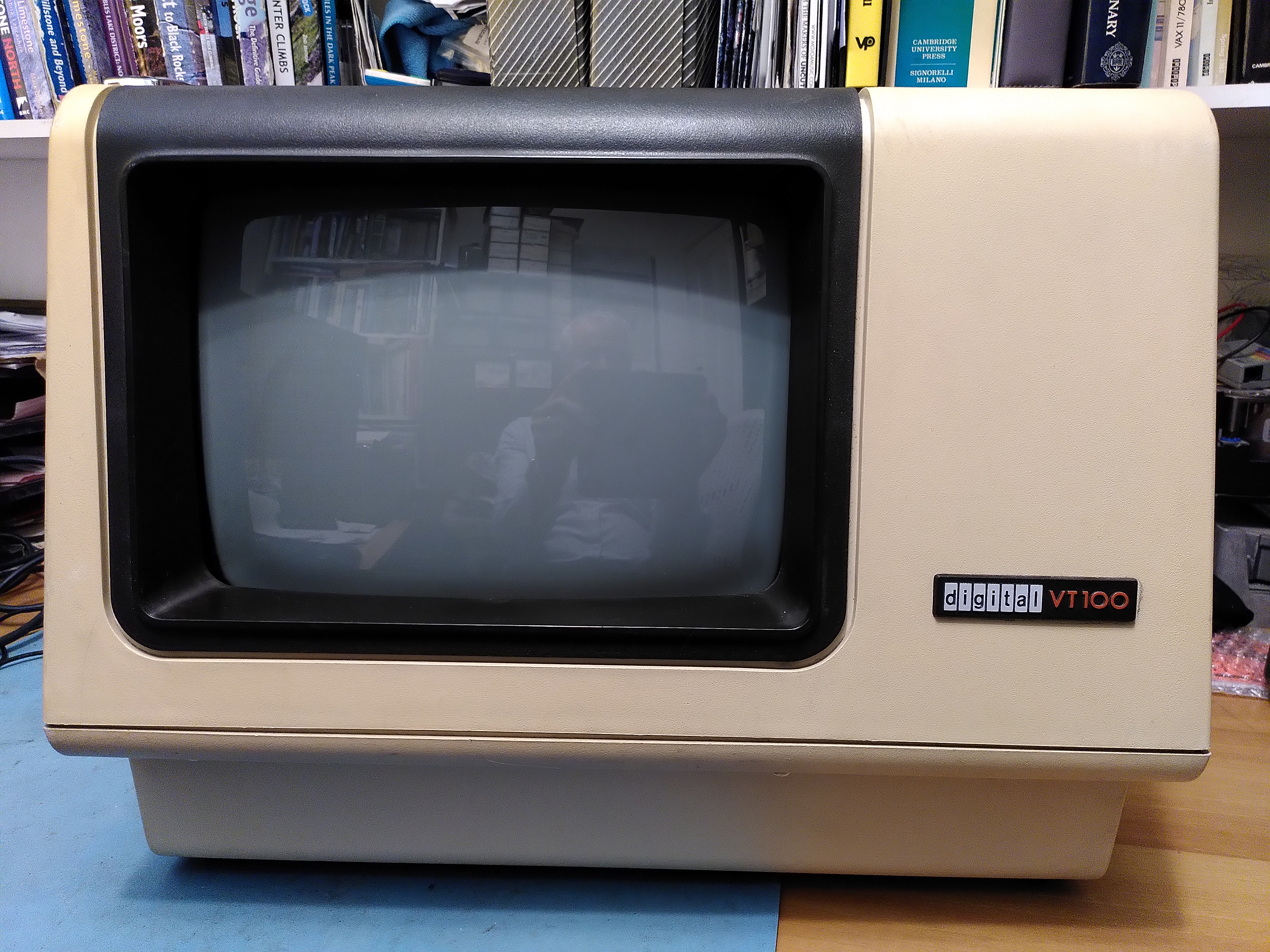
I have been repairing a VT100 that I acquired a while ago. I have got it to the point where it works except for the actual video display, as described in a previous post. I wanted to try to get it to show an image on the CRT.
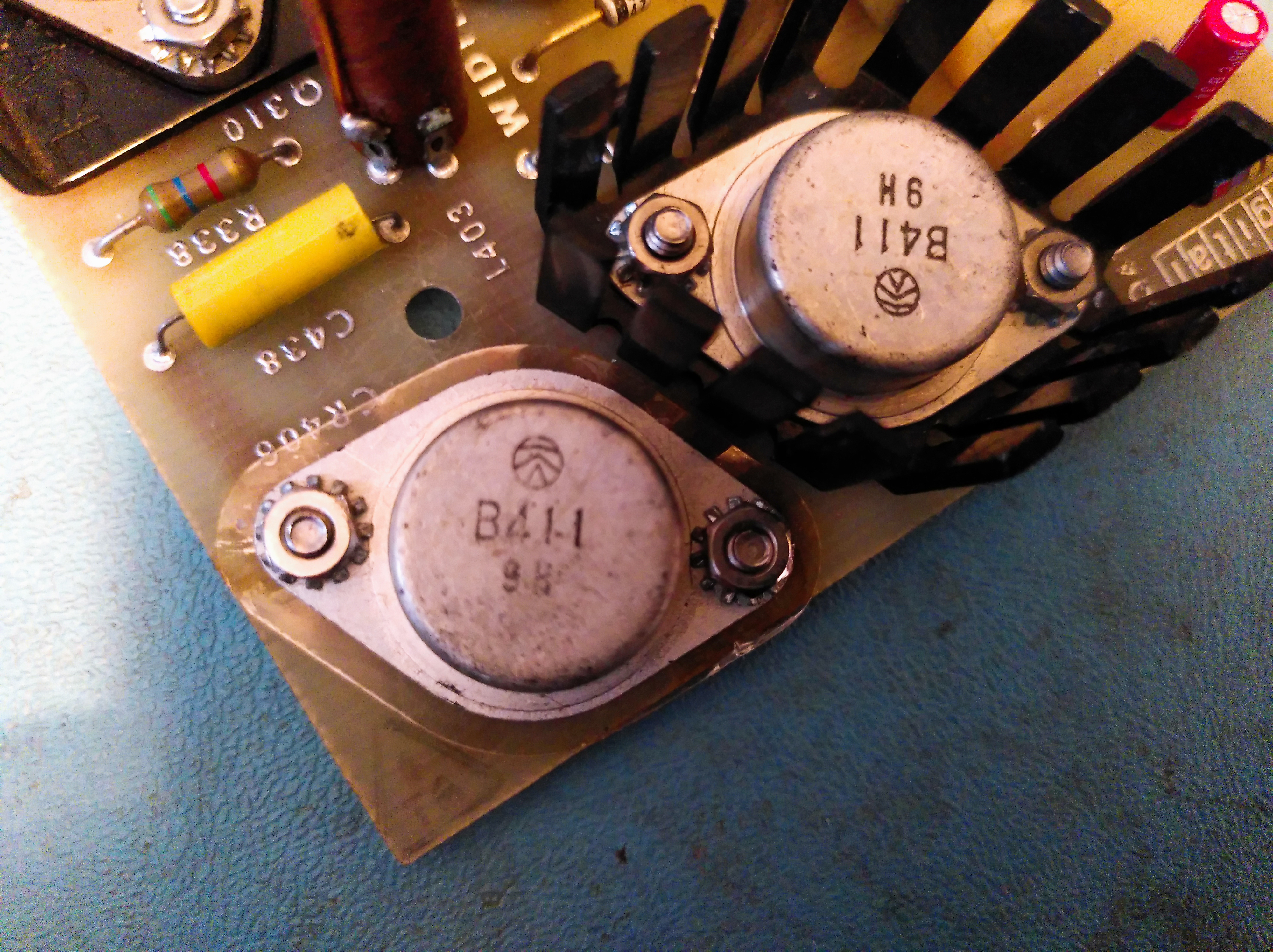
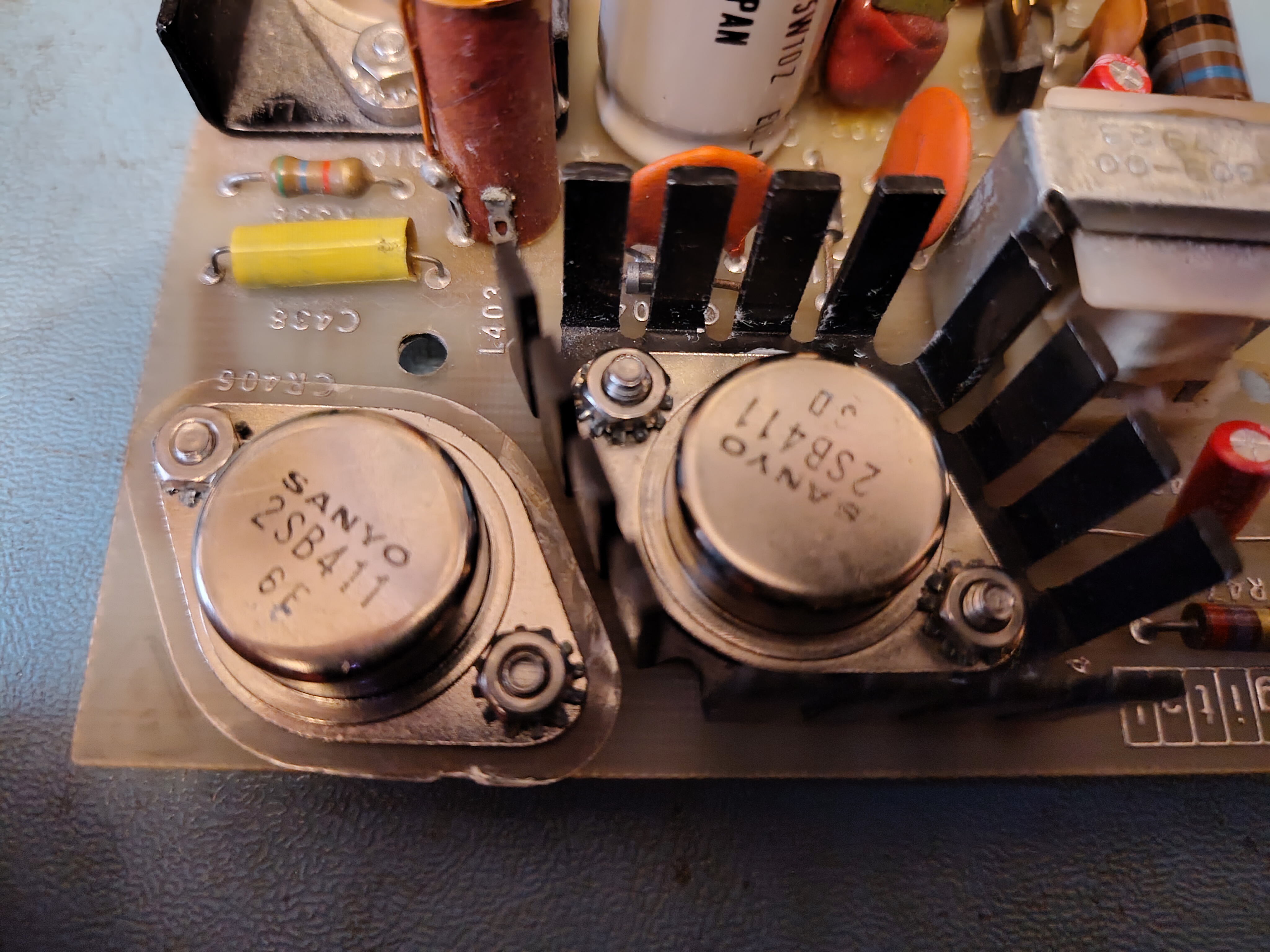
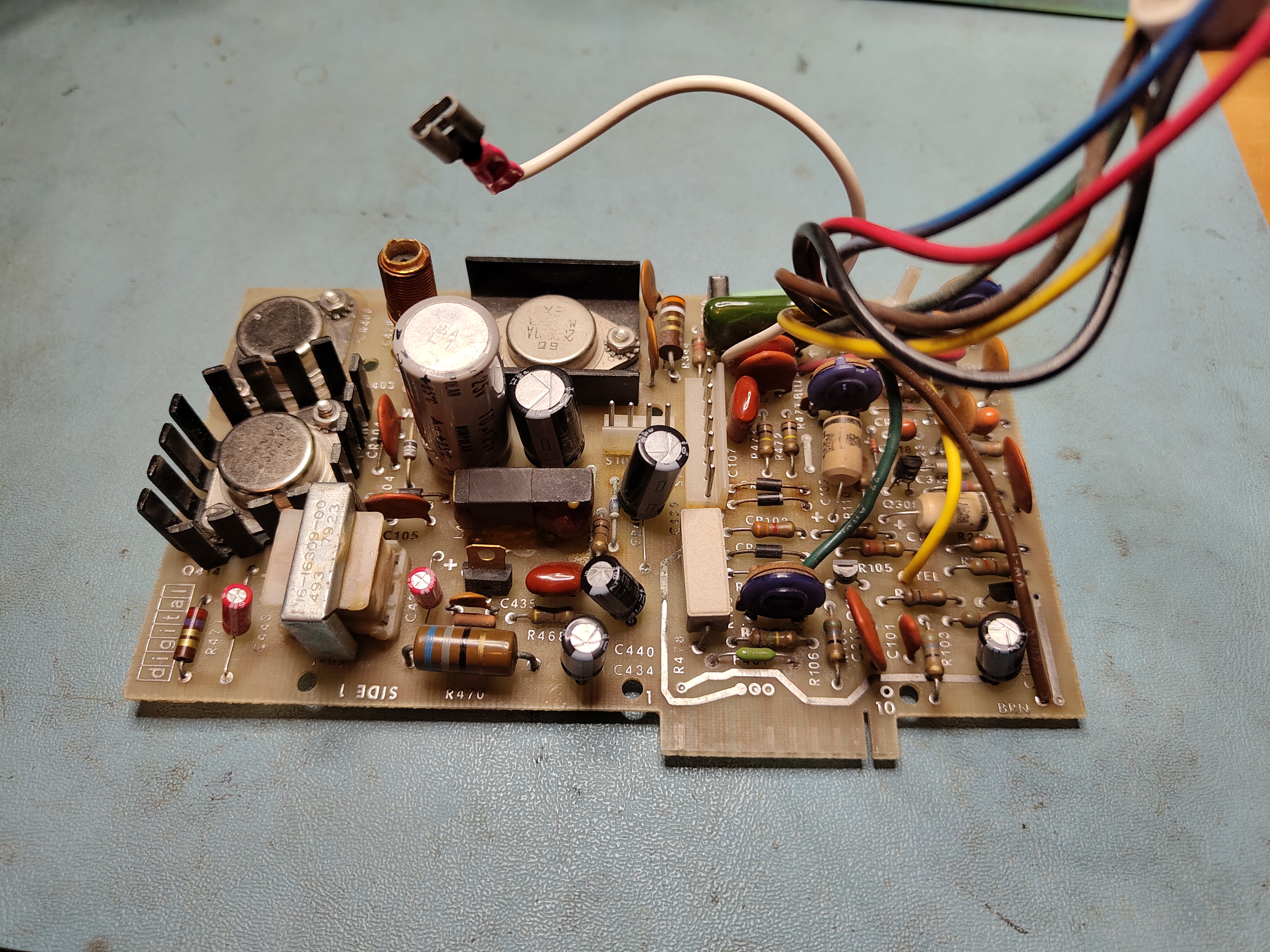
The first problem is that my Elston monitor board does not match the schematic in the February 1982 print set. My VT100 seems to be an older version described in the March 1980 print set but this print set does not include the schematic for the monitor board. My board has two transistors in a TO3 package for Q414 and CR406. The February 1982 print set has quite a different layout. This is my monitor board after I had replaced some of the electrolytic capacitors:
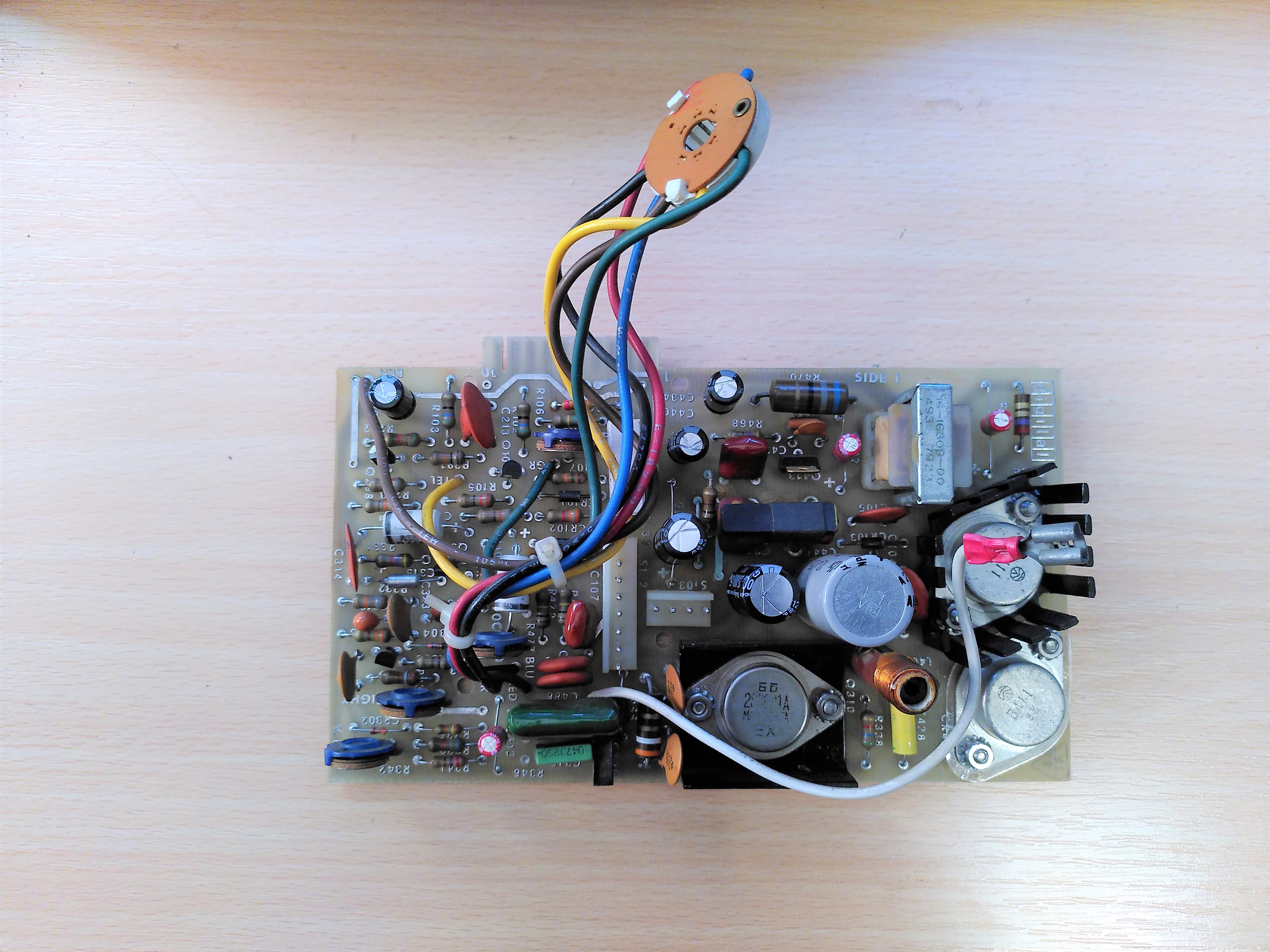
It turns out that Q414 and CR406 are actually 2SB411 germanium transistors. A version of the schematic exists for the Micro-Term MIME-1 terminal on p53 of the PDF of the technical manual.
The first problem I found was that the monitor board did not seem to be receiving any power. This turned out to be the fuse, F401, that has blown. I guess the fact that this had blown was a bit suspicious, there was no obvious reason why it might have failed, but the worry here is always the flyback transformer.
Initially, on advice, I replaced the fuse with a 12V car bulb to act as a current limiter. This showed there was no dead short on the output side of the fuse. After replacing the fuse I switched on the terminal. There was no glow from the filament and I thought I could smell burning, so I switched it off immediately. The fuse remained intact though.
On further advice I tried removing various parts. It was at this point that confusion reigned about Q414 and CR406 because they did not measure like the transistors in the February 1982 schematic. It took some time to realise they really are germanium parts and that my board is an older version.
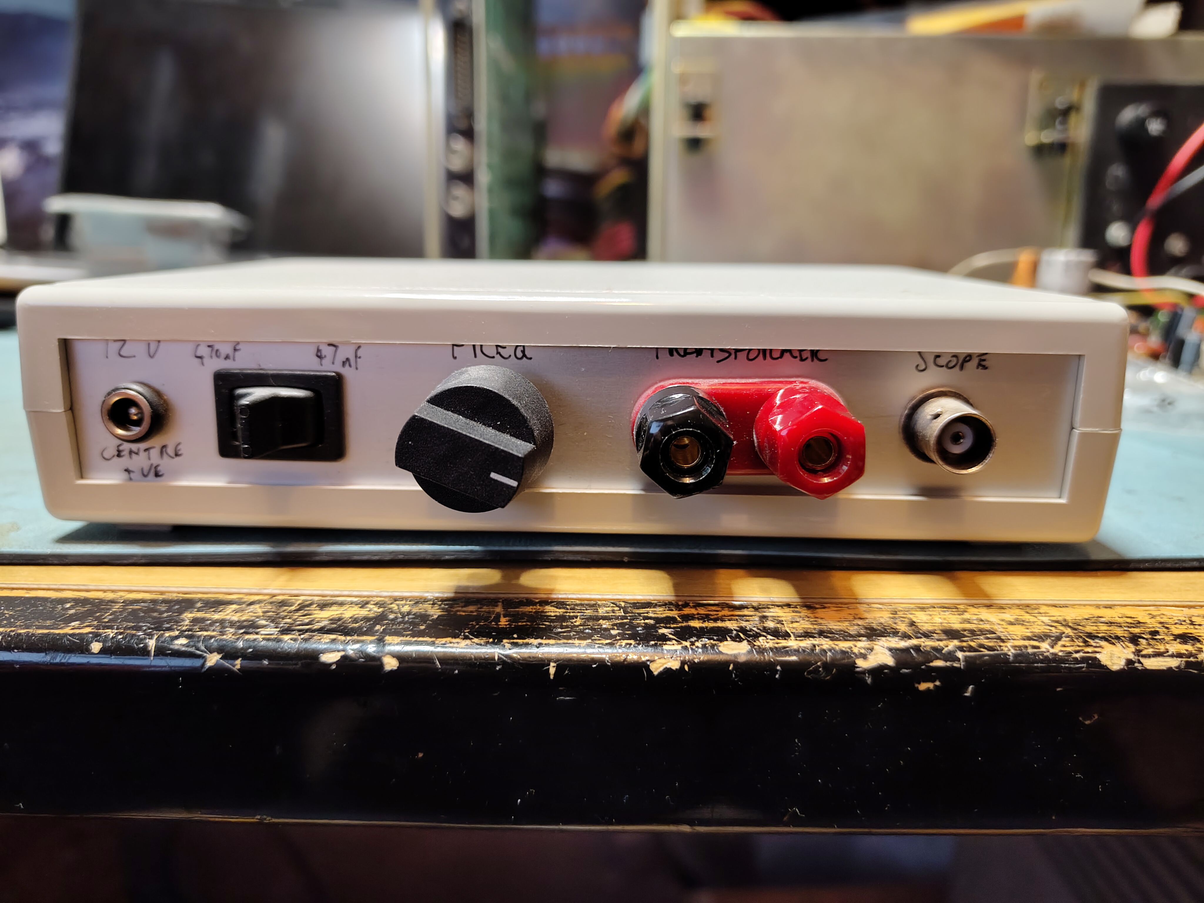
To test the flyback transformer for shorted coils I needed to conduct a ringing test. I was sent the details of a circuit that can be used to do this. The circuit was described in an article published in the September 1993 issue of Television magazine. I built the circuit and put it in an enclosure. This is my ringing tester:
I tested each winding following the schematic to identify them. These are the results:
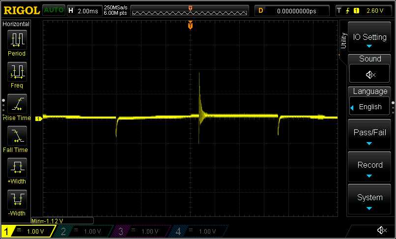
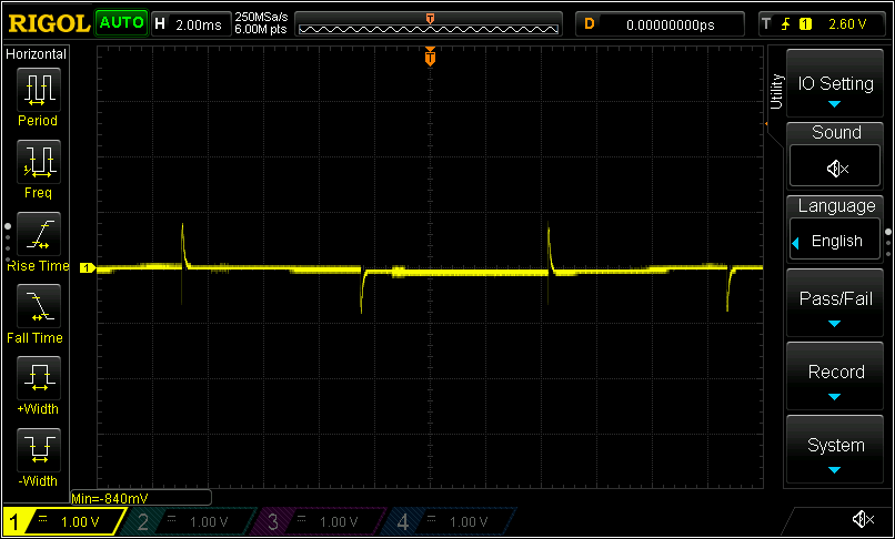
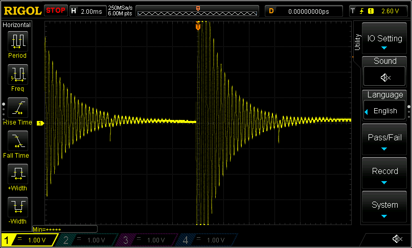
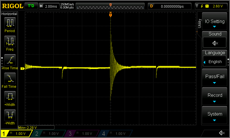
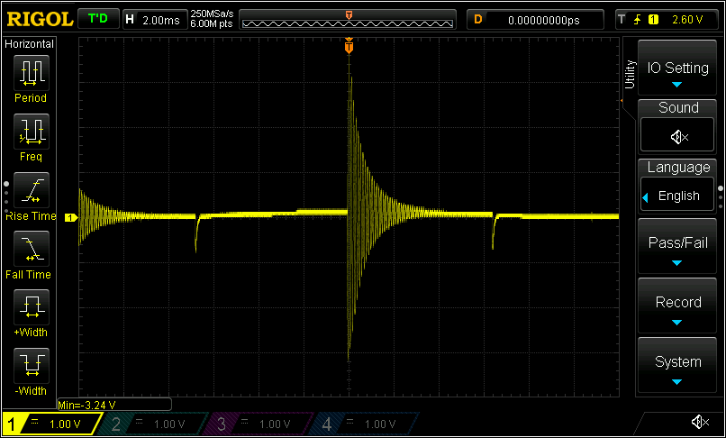
The Brown-Red and Black-Violet coils only have a few turns so all these results appeared reasonable.
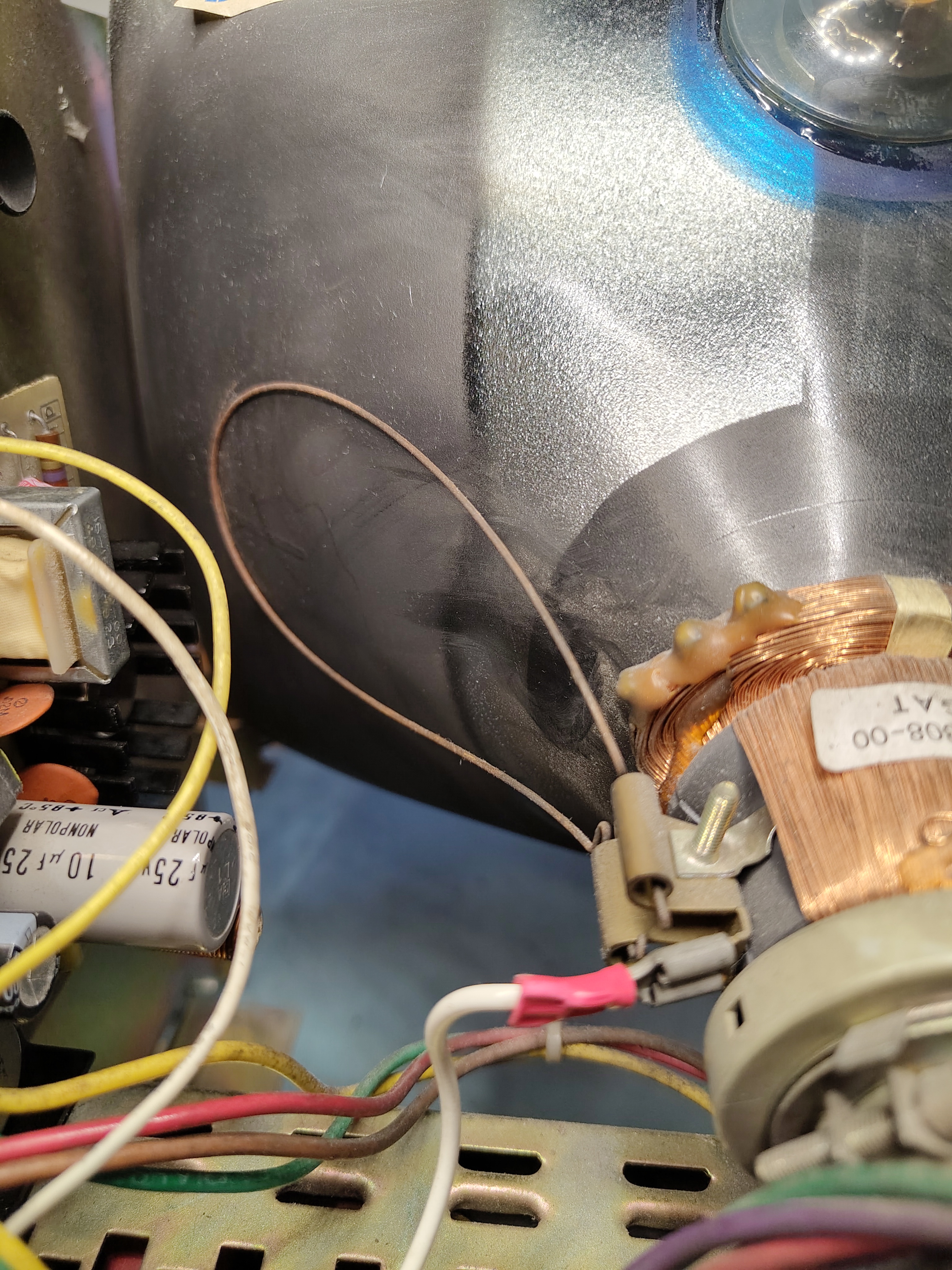
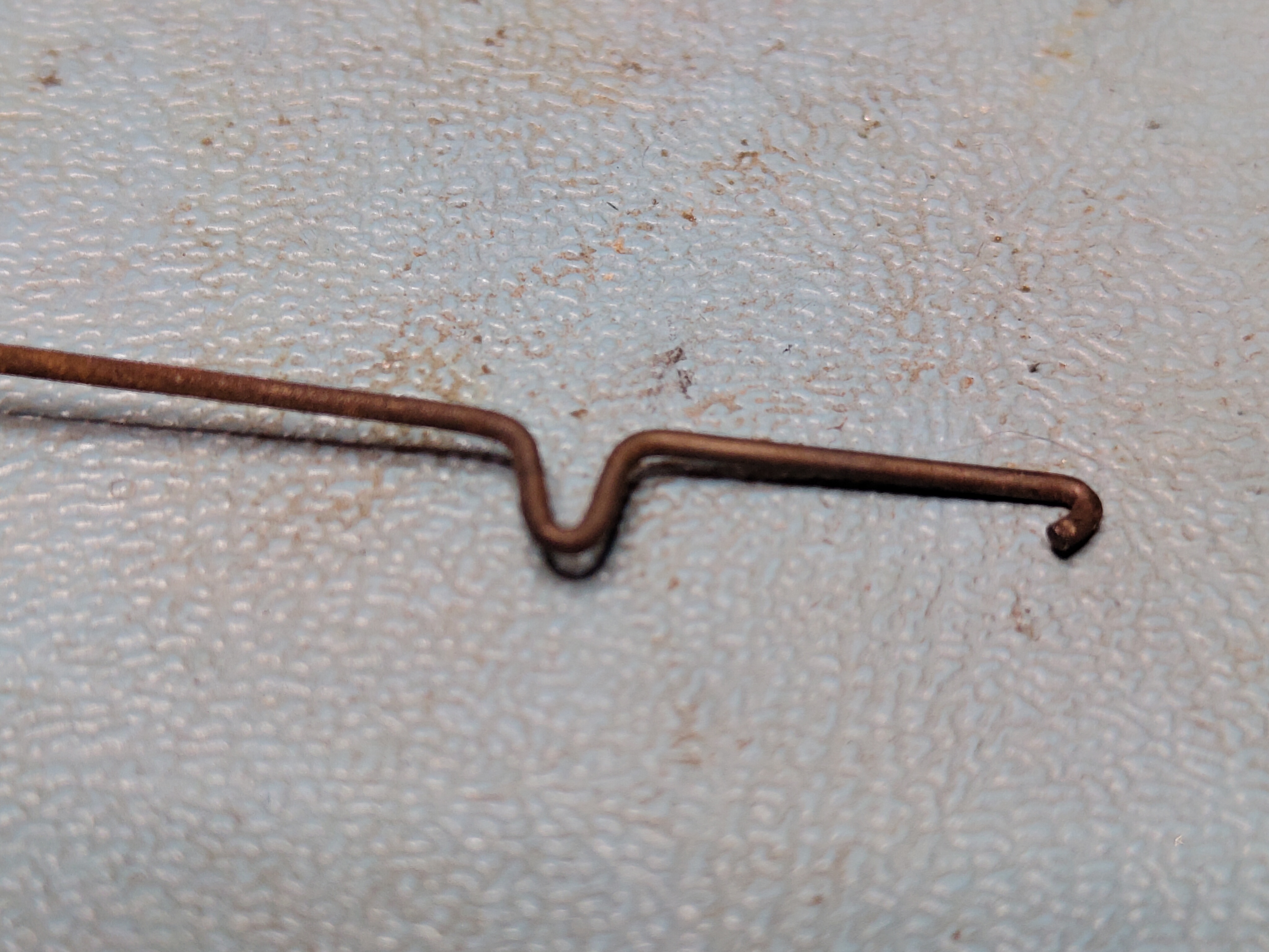
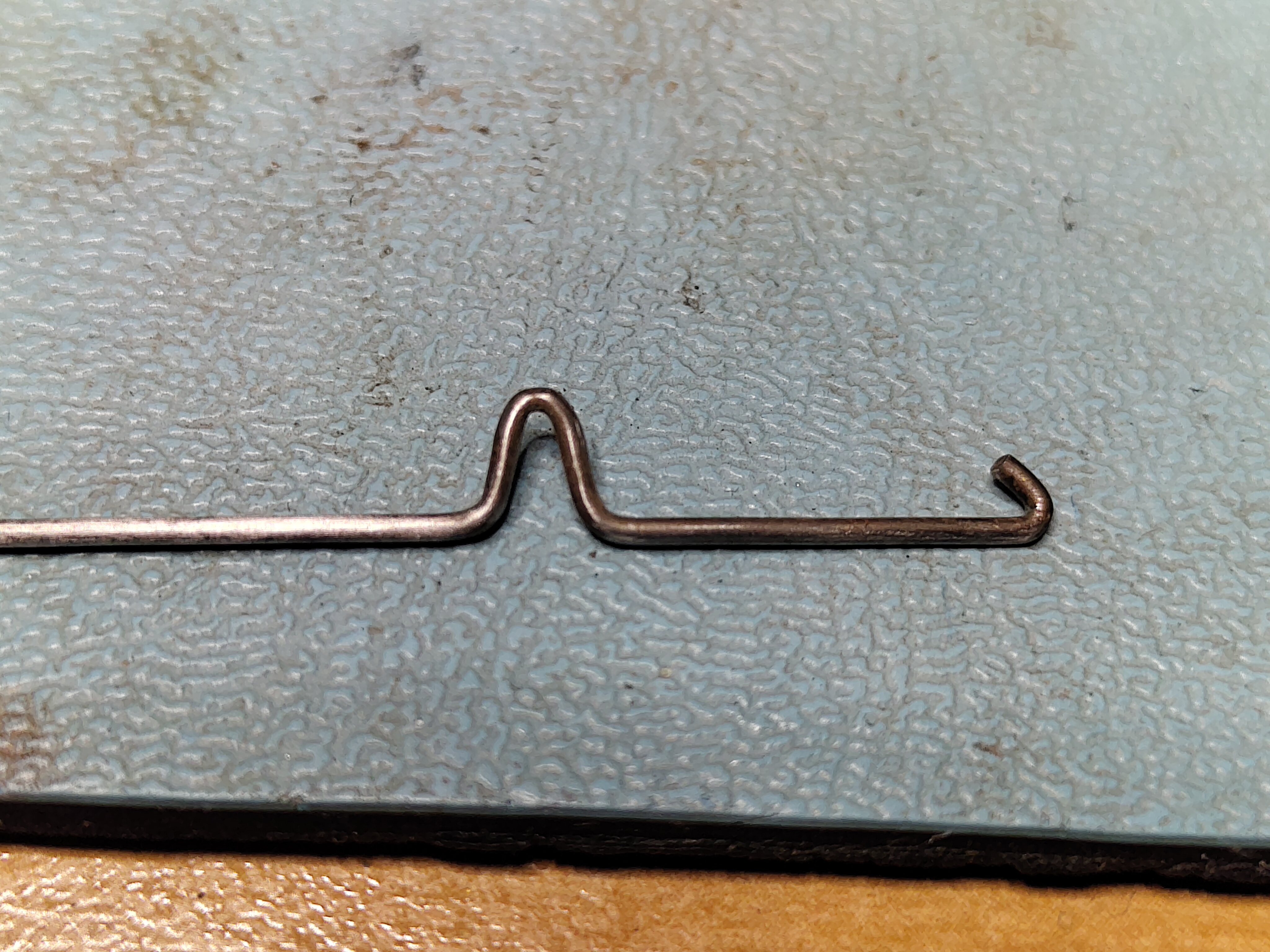
As mentioned above, the germanium transistors, Q414 and CR406, were not measuring well. I have a Peak Atlas DCA 55 component tester, it identified them as three terminal bicolour LEDs. I sourced some new old stock replacements. These were identified correctly as germanium PNP transistors so I fitted them, applying some fresh TIM to the one with the heatsink, and decided to risk trying again. I also had to repair the wires going to the neck of the tube, metal fatigue had broken some of them where they were attached to the board, this may have been why the filament had not glowed in earlier tests.
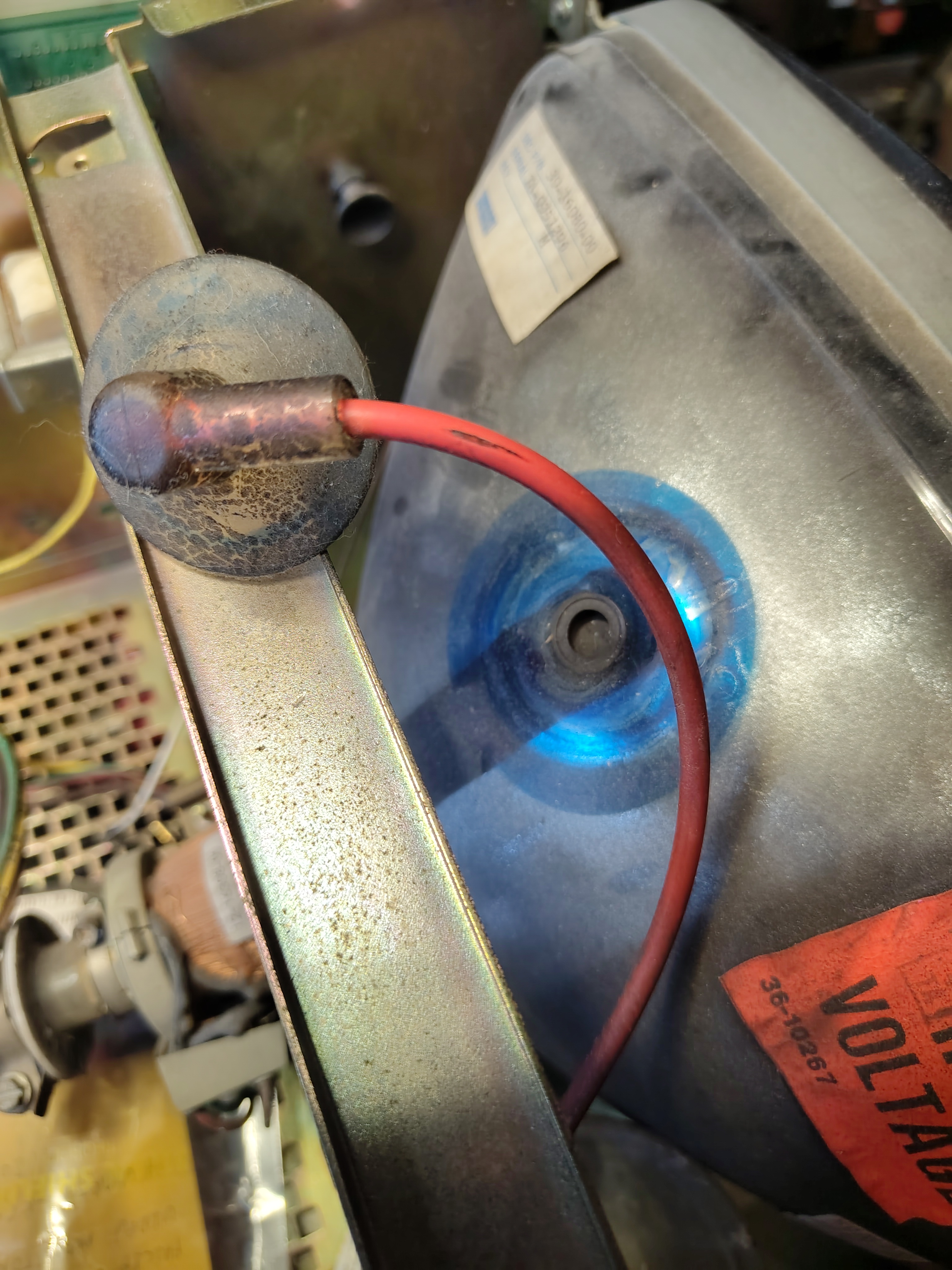
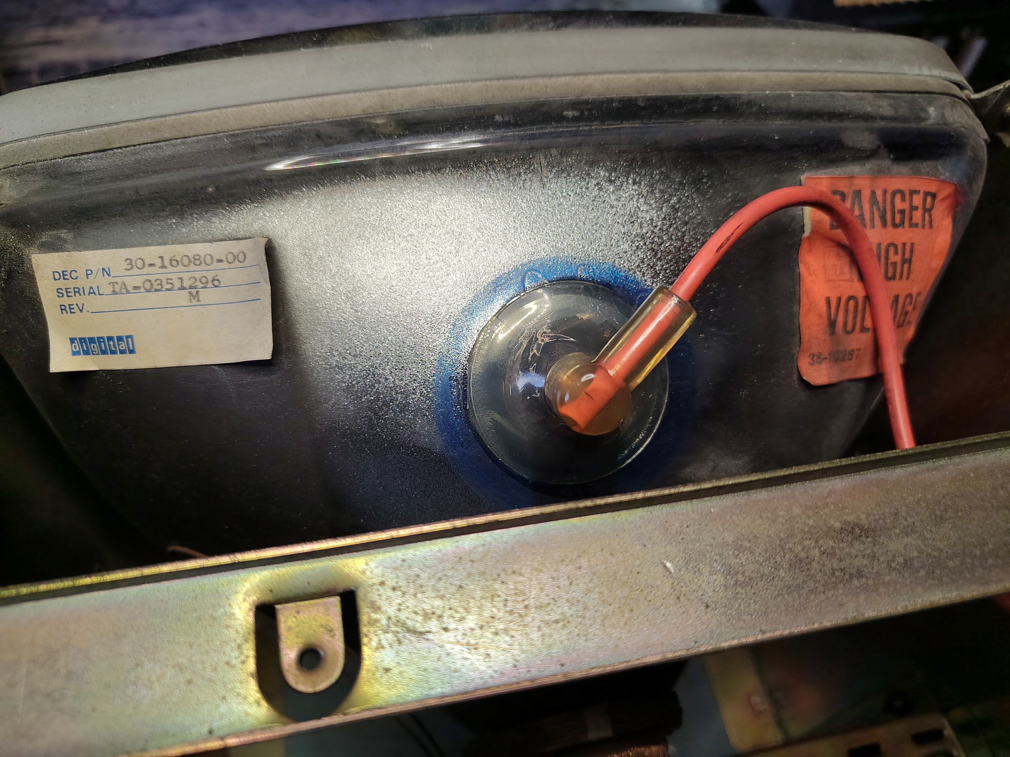
I cleaned up the anode cap and the area around the anode cap on the tube itself, finally and applying fresh silicone grease. Then I noticed that the grounding wire that contacts the aquadag on the outside of the tube was corroded and not making electrical contact, so I cleaned that up too and checked it was making good contact.
I switched on the terminal but got the same result, a faint crackle and a smell of burning. So I switched it off quickly.
With yet more advice, the focus then moved to checking if there was too much current being pulled through the flyback. First I removed C102, CR409 and C104 to eliminate excess load on the outputs. This made no difference, there was still a burning smell and I could not keep the terminal switched on for more than a few seconds to avoid further damage. Then I measured the voltage drop across R478. This showed that 3.2A was being drawn through the primary coil of the flyback. At last a fault that can be looked at more closely.
I did a few more tests but the inevitable conclusion was that the flyback transformer itself is failing. Most likely the insulation on the wires is breaking down at high voltages, leading to excessive current draw. This was the worst possible outcome as these parts are unobtainable.
I put the Monitor Board back in the terminal with everything connected except the flyback transformer.
So that is the end of that, I have to be content that I got it to work with the external video connector. My best hope is to find a replacement flyback one day from another VT100. It seems that making a new one is highly impractical.
