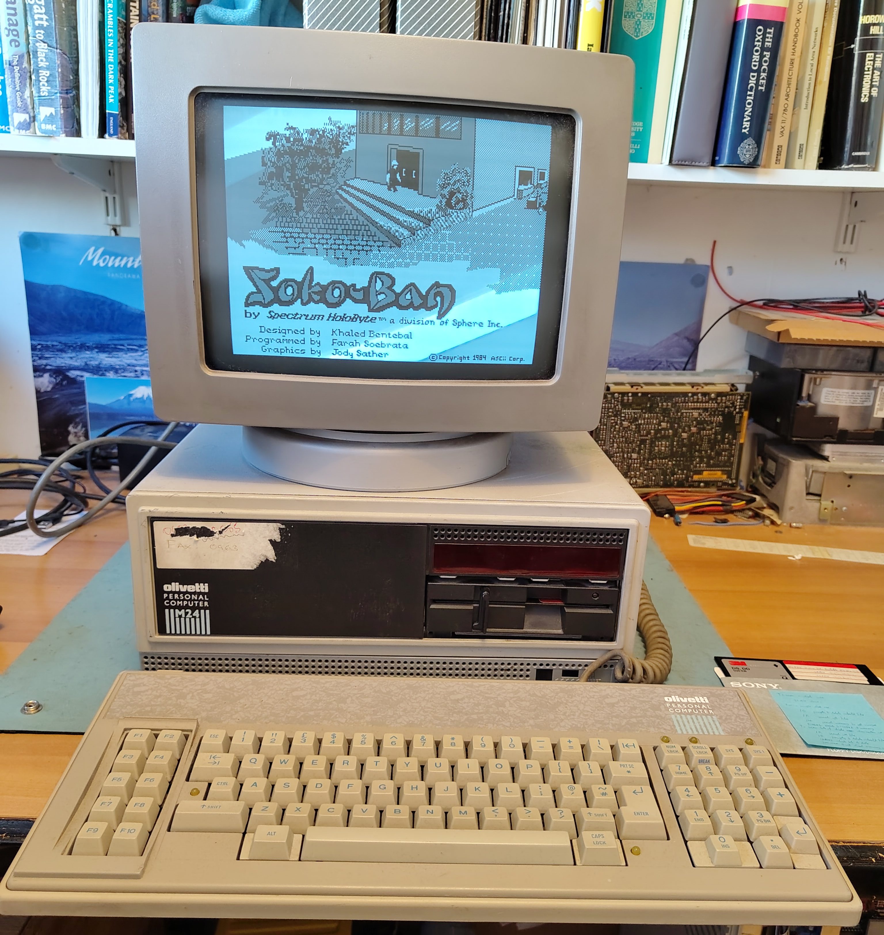
I have had two Olivetti M24s for a while, one with monitor and keyboard but no HDD controller and one just the base unit with a HDD controller but no drives, not even the floppy disk drive. Recently I acquired a second keyboard (ANK 2886). I got the keyboard partly because the original (ANK 2462) seemed a little unreliable, although it just turned out that it needed a bit of attention. I had put together a working system from the combination of the two machines and the machine worked nicely.
While using the machine I switched it off because I don’t like leaving vintage machines powered on while unattended. When I came back it would not power on. There were no lights on the front panel or the keyboard, and there was no display. Only the fan turned.
I suspected a power supply failure. It is an ALI LA16. I opened the case and checked the power in the Molex connector for the disk drives. The 5V pin was at 0V and the 12V pin was about 2V, this was with all loads connected. So clearly the power supply has failed. To get the PSU out I followed this procedure, all the orientations are facing from the front of the case:
- Disconnect the power cable to the drives from the PSU.
- Pull out the drive cage (use a screwdriver to lever away the locking mechanism on the underside of the cage).
- Remove power, interface and earth wires from drive cage and remove the drive cage.
- Remove the HDD controller (if too close to the PSU to reach the screw).
- Disconnect motherboard power cables.
- Disconnect the two 12V connectors on the left (they just pull out).
- Disconnect earth wire from base at the front of the PSU.
- Remove screw that holds down the PSU on its left.
- Remove the fan cover (two screws at the bottom).
- Disconnect the fan (I marked one of the connectors and took a picture so I can reconnect them the right way around).
- Pull the PSU out.
To open up the PSU itself:
- Remove the two screws at the top of the panel with the mains connectors and switch.
- Remove the screw on the side panel that is not connected to the earth wires.
To remove the boards:
- Remove the screws holding the earth connections at the side and at the connectors to the motherboard.
The schematic for the PSU is in the Theory of Operation manual, but the part numbers don’t match up to the markings on the boards, so someone on VCF has produced a marked up version which I have copied here for those who don’t have an account on VCF.
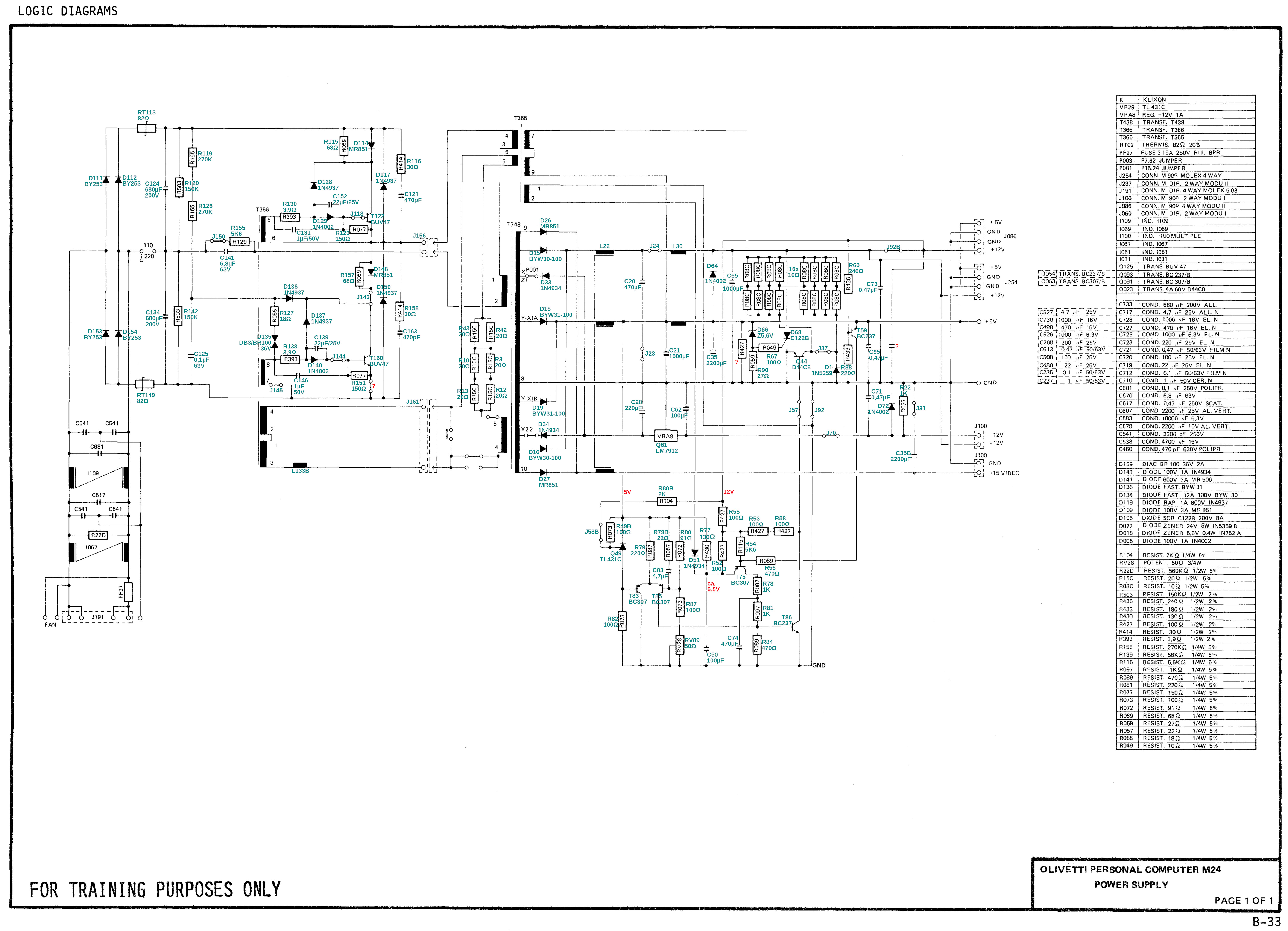
Note that there are a couple of errors:
- R88 is 180R, not 220R
- C21 is 10,000uF, not 1,000uF
During my work at trying to find and fix the fault I found that sometimes the PSU would actually work, but then at other times the outputs would stay resolutely at 0V. Also, while trying to test different parts, I noticed that one of the connectors for connecting between the two boards was loose and actually came away. I think this might have been marginal and in my attempts at separating the two boards it finally came away. I re-soldered it, but the PSU still wasn’t working reliably.
I tested the capacitors C21 and C35 on the +5V output and found that they seemed to measure inconsistently and one seemed to have a barely discernible bulge. I decided to replace them. When I replaced them the PSU started to work. However, in testing further, I found that the PSU did again stop working, but leaving it alone for a while seemed to clear it up. It feels like it is working better but almost certainly not fully fixed. For now it seems to work reliably, and I have had no further failures.
