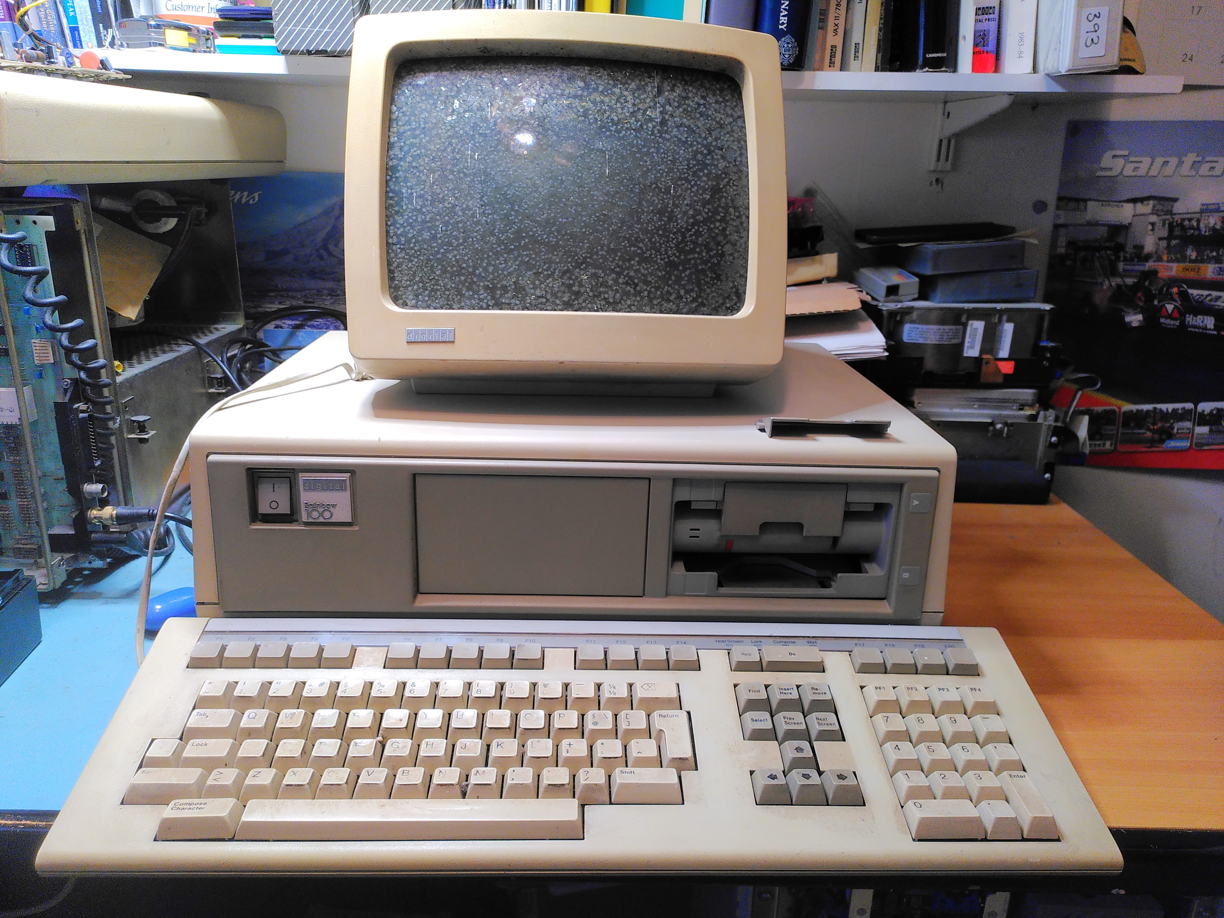
I acquired a Rainbow 100A a while back. It had a few problems:
- Video RAM fault.
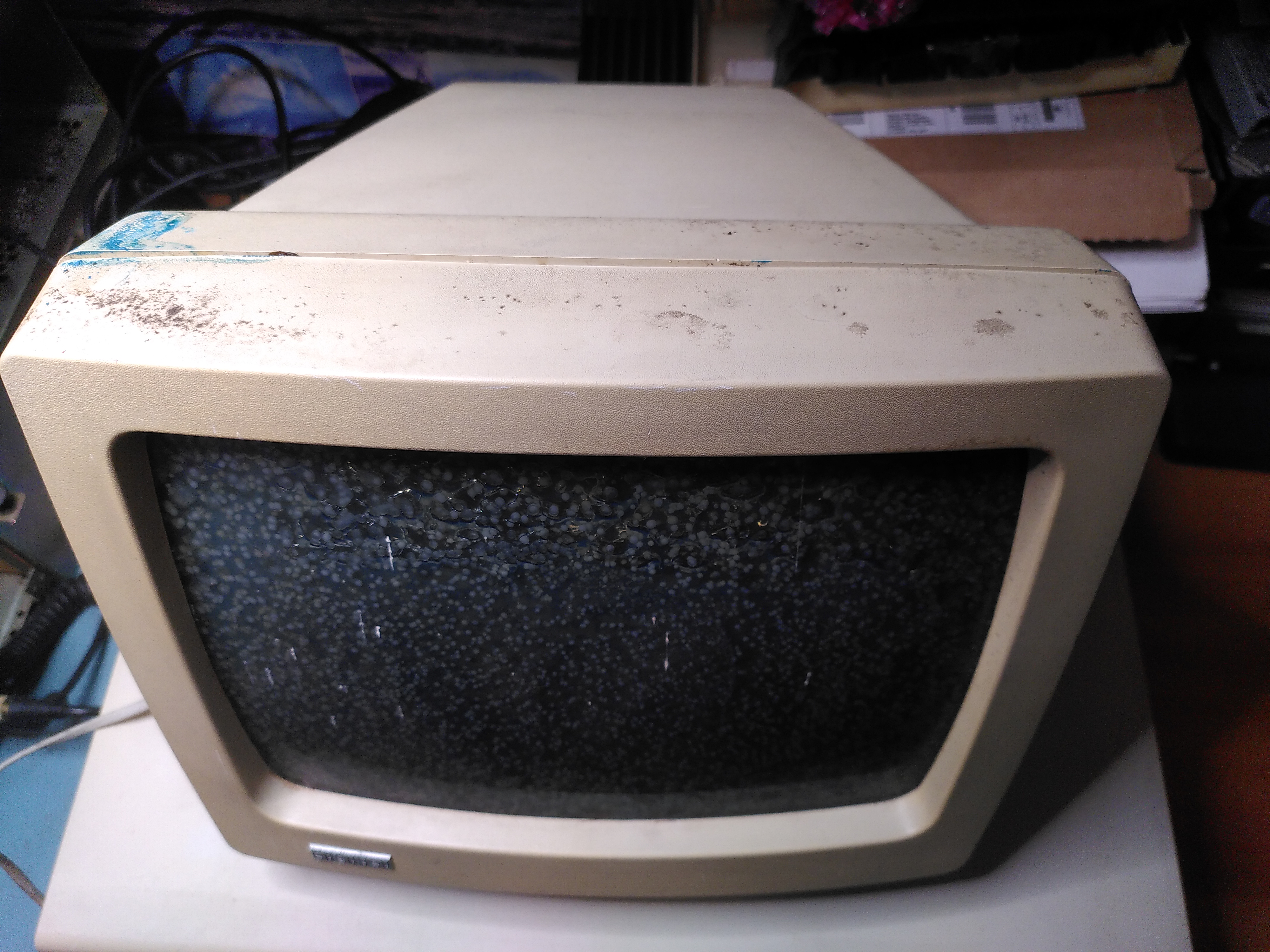
- Screen cataracts.
- RX50 floppy disk drive door adrift.
- RX50 would not read disks
It also came with a Floor Stand, an LA50, manuals and disks.
PSU Inspection
Before switching it on I checked the PSU visually, mainly for any bulging or leaking capacitors. Once I was satisfied with this I was able to power it on. I checked the ripple on the power supply, that looked fine too.
Video RAM Fault
The diagnostic LEDs on the back were showing the code 1110110 indicating a Video RAM fault. After a few sanity checks I got the logic analyser out. At first I put the probes on the RAM chips themselves (E121-4). It looked like it was only writing to addresses 0 and 1 of the lower 2K of the screen RAM (chip E122).
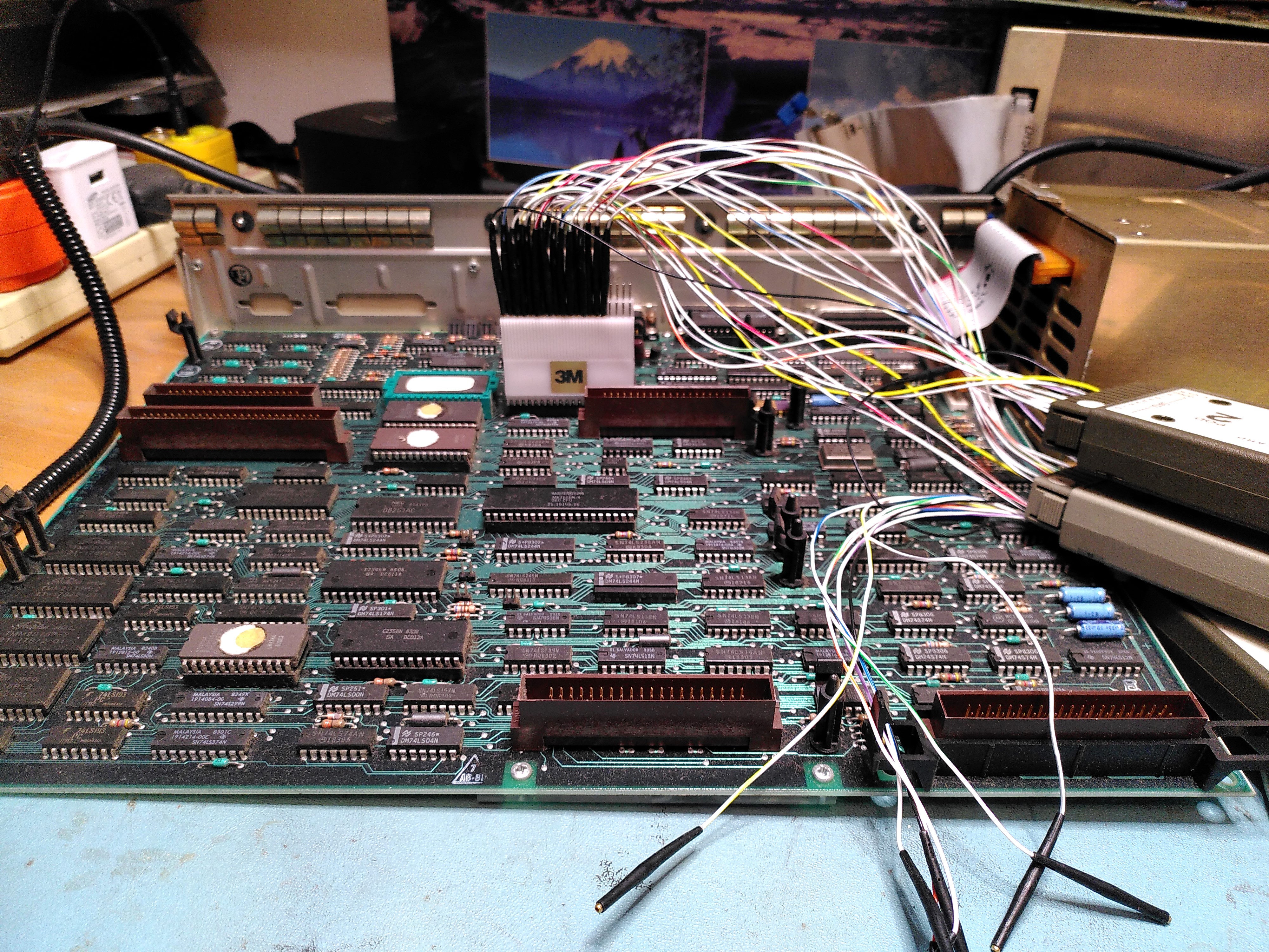
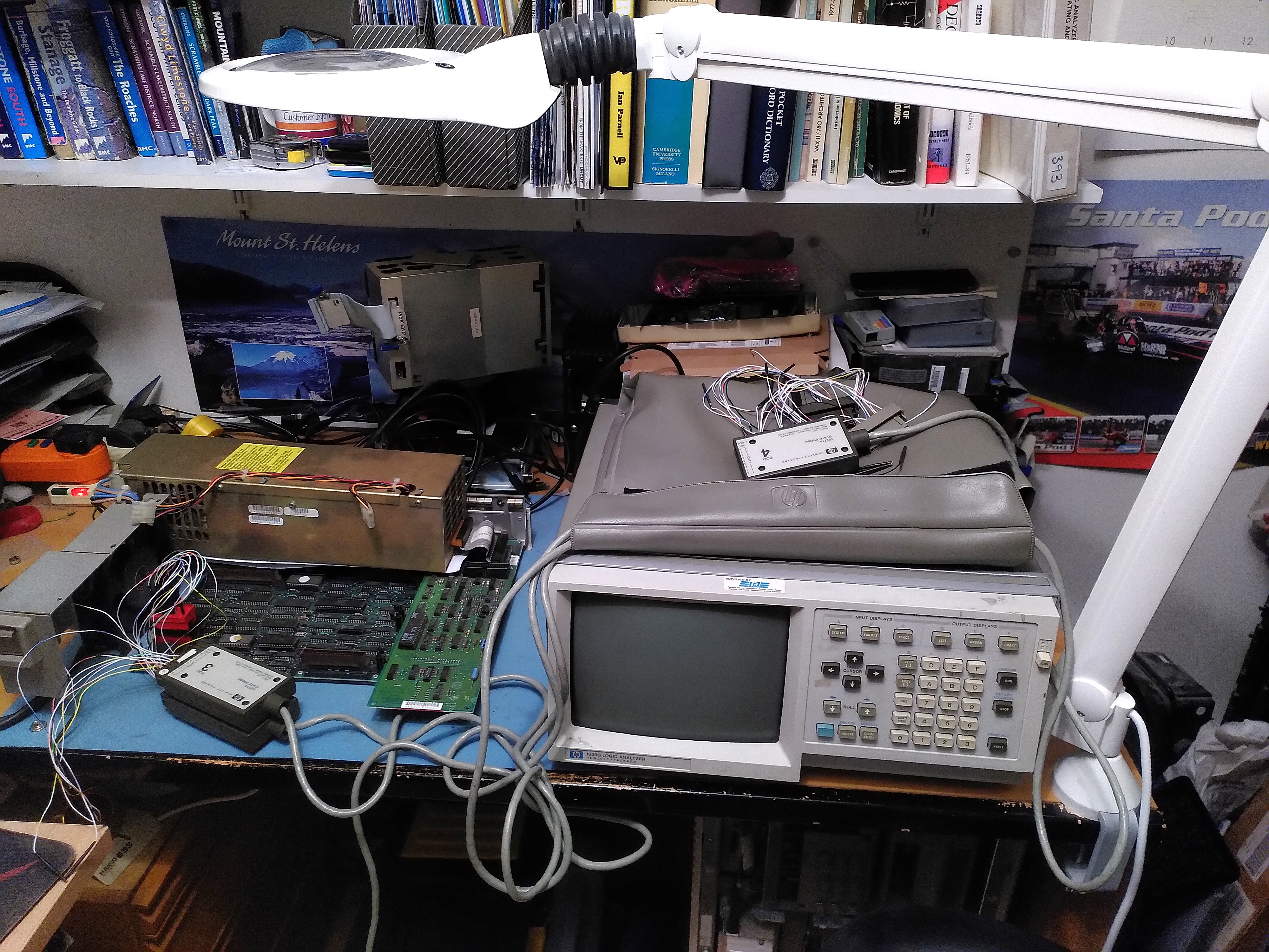
As I was not confident of my ability to capture the reads and writes on the RAM I decided to try to get an address trace from the 8088 microprocessor instead. There I could be more confident that I was triggering on the correct signal (negative edge of ALE) to capture the addresses. I could not however tell if the addresses were reads or writes. After triggering on the Video RAM address range I confirmed that it was only accessing addresses EE000 and EE001.
To be doubly sure I got the system board out of another Rainbow (a 100B) and did the same thing. There I saw the Video RAM being tested with addresses being accessed in descending order.
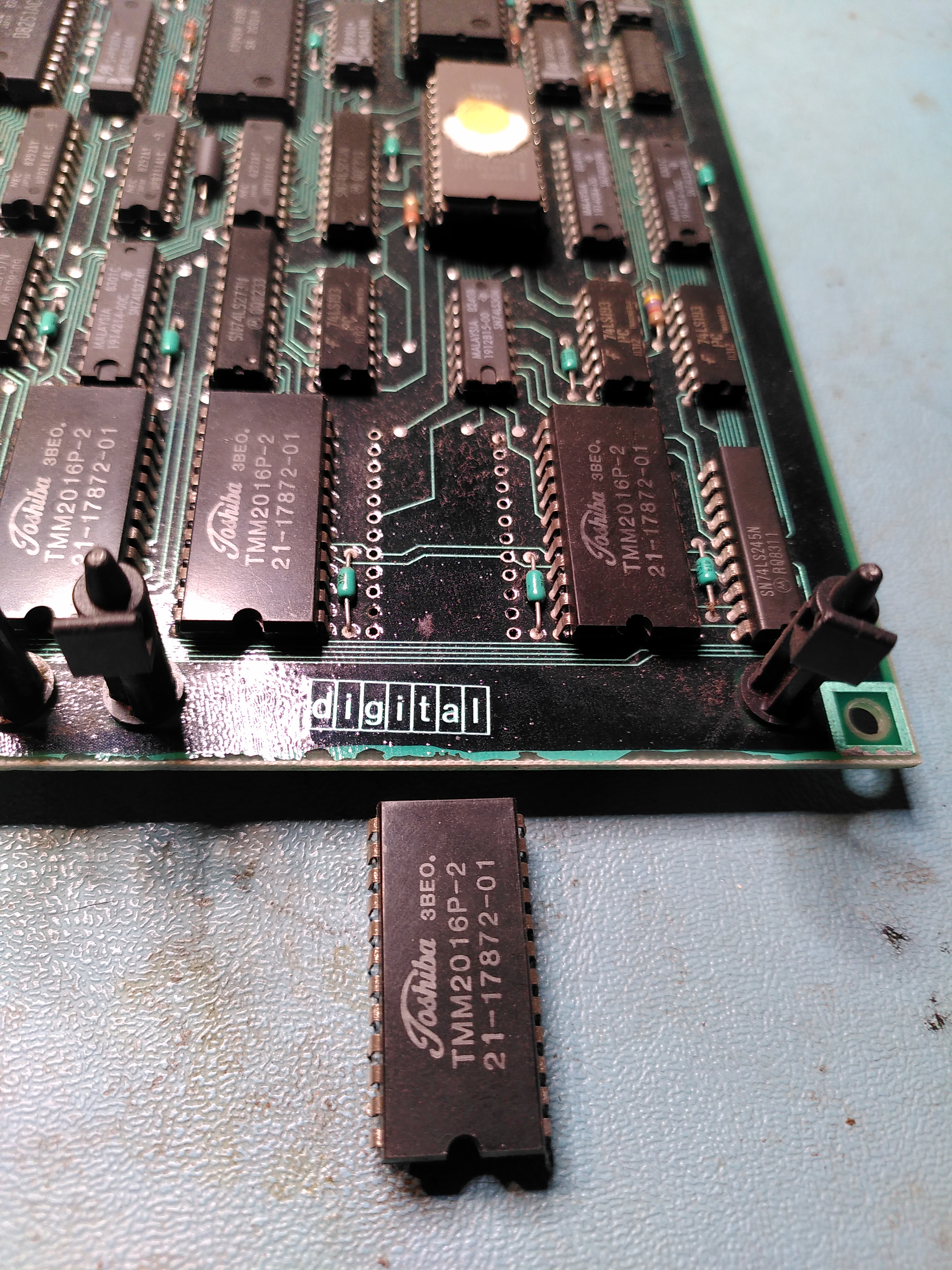
I decided that E122 must be faulty. This is a TMM2016P-2, I found a replacement marked TMM2016P, with no suffix. I don’t know if the replacement is a higher or a lower spec. However I replaced it.
After doing this, with the system board still on the bench, with no floppy disk controller and no monitor connected, the diagnostic LEDs showed a lot more activity, finally settling on the code 0110101. This is Message 1 “Main Board Video”. I speculated that this could be because the monitor was not plugged in. So I connected a VR201, although not the one with cataracts. Sadly it displayed the same message.

This was a bit puzzling because it is obviously good enough to display a message.
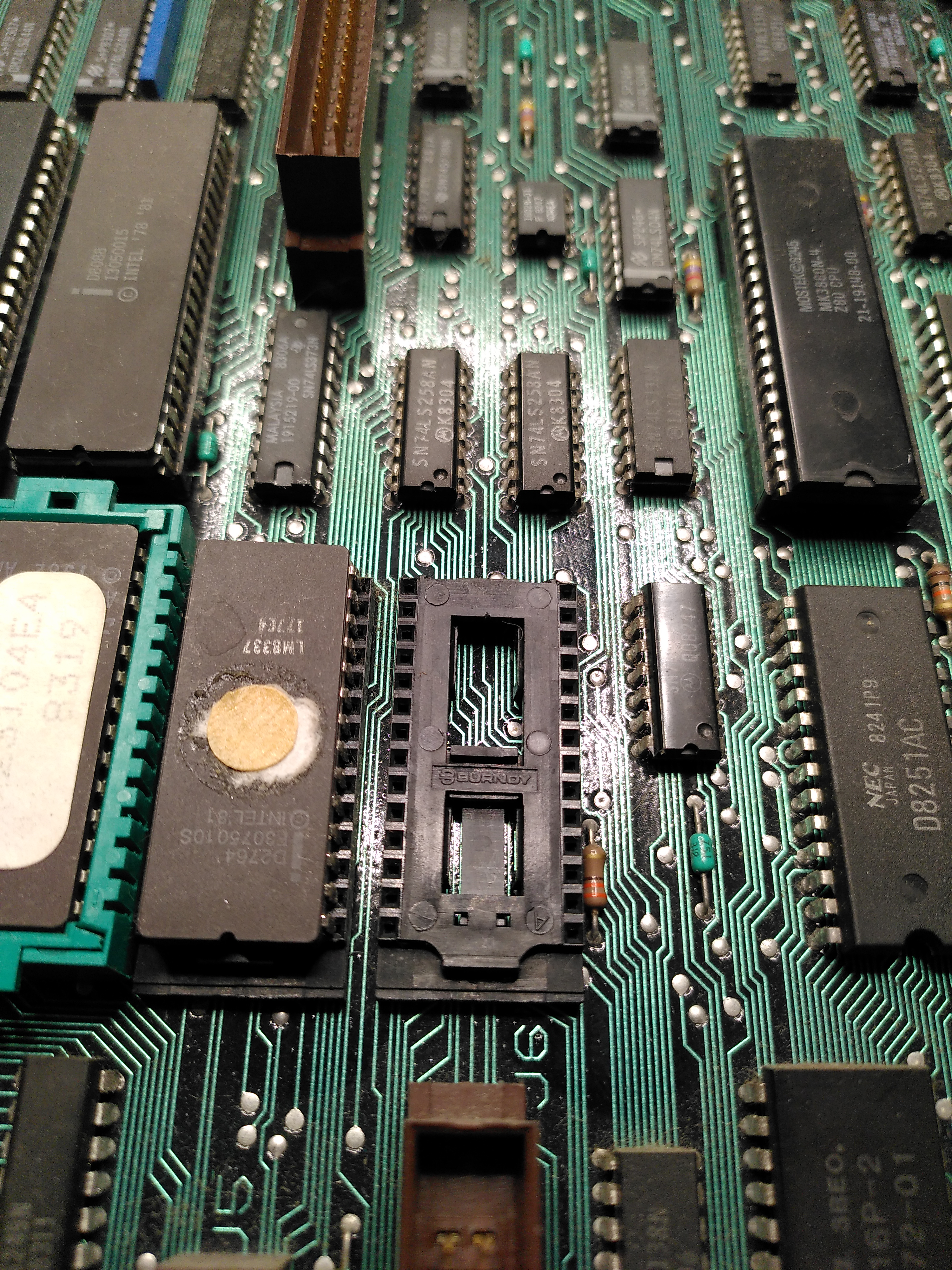
I decided to check the ROMs. This was a lot harder than I expected because the ROMs are mounted in a QIKEJECT socket. At first I didn’t know how to remove it despite a diagram in the Technical Manual. I realised that you need to put a screw driver in the slot and gently push down to release a clip, this allows the chip to be moved across and then it can be lifted out.
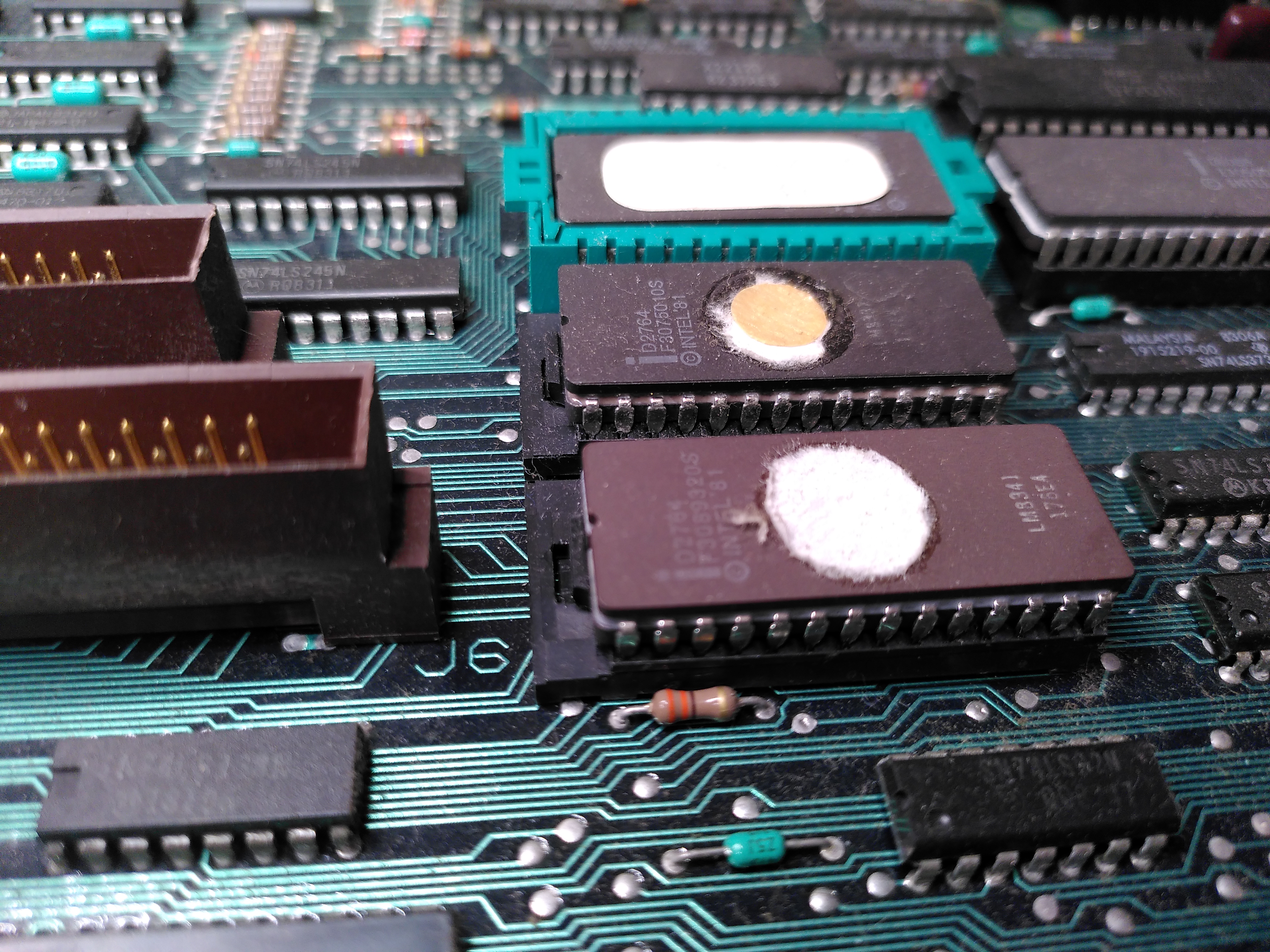
I checked the ROM with my programmer and the contents matched those of an image I found at archive.org.
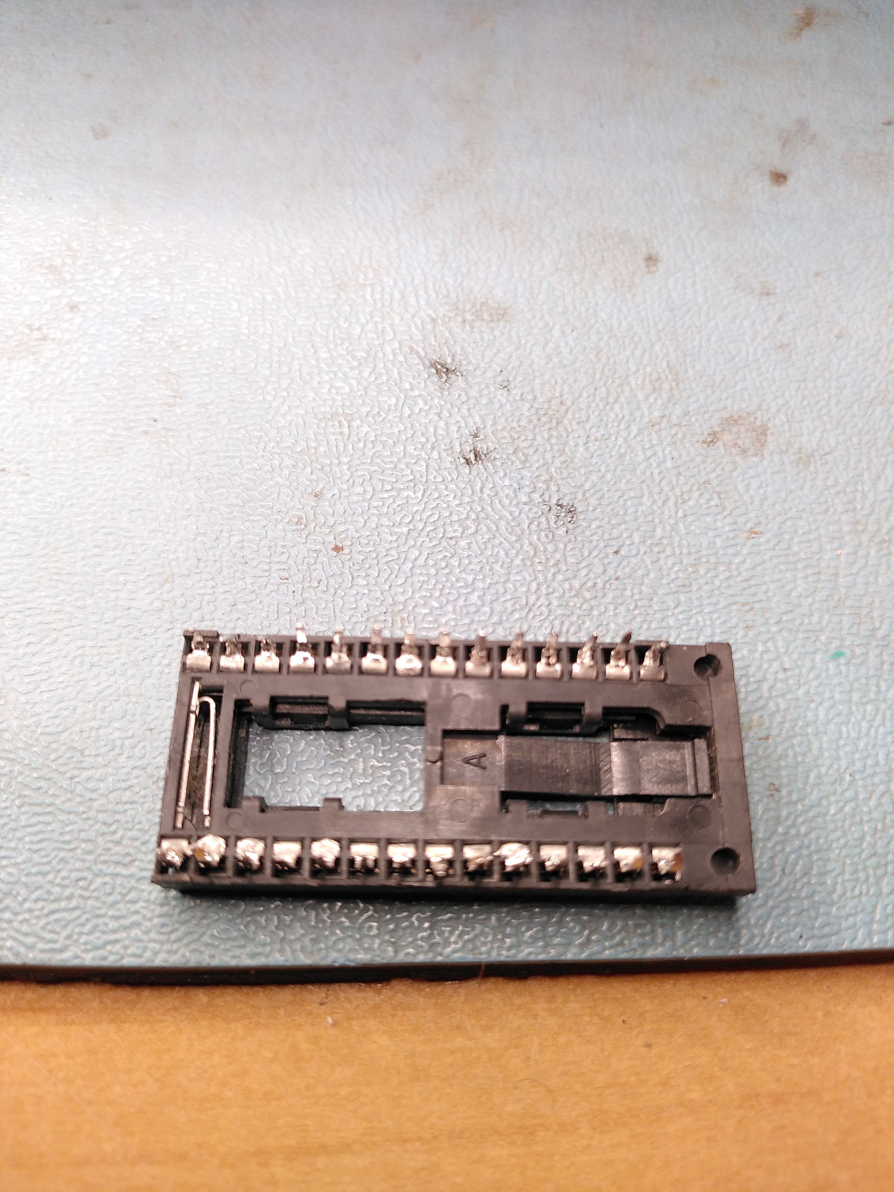
Putting the ROM back was another story. I could not get the socket to move back to the locked position with the ROM inserted. It would move back when the ROM was not inserted, but there was nothing I could do to persuade it to lock with the ROM inserted. I asked on the forums at Vintage Computer Federation and it seems to be a common problem. So I de-soldered the socket and replaced it with an ordinary socket.
Because of the difficulties with the socket I decided that for now I wouldn’t check the other ROMs.
After a lot of work with the logic analyser, following the attributes from the Attribute RAM, through the Line Buffer and into the DC012 I finally discovered that one of the Line Buffer chips was not working reliably. This is a 2114 static RAM labelled E100 on the schematic.
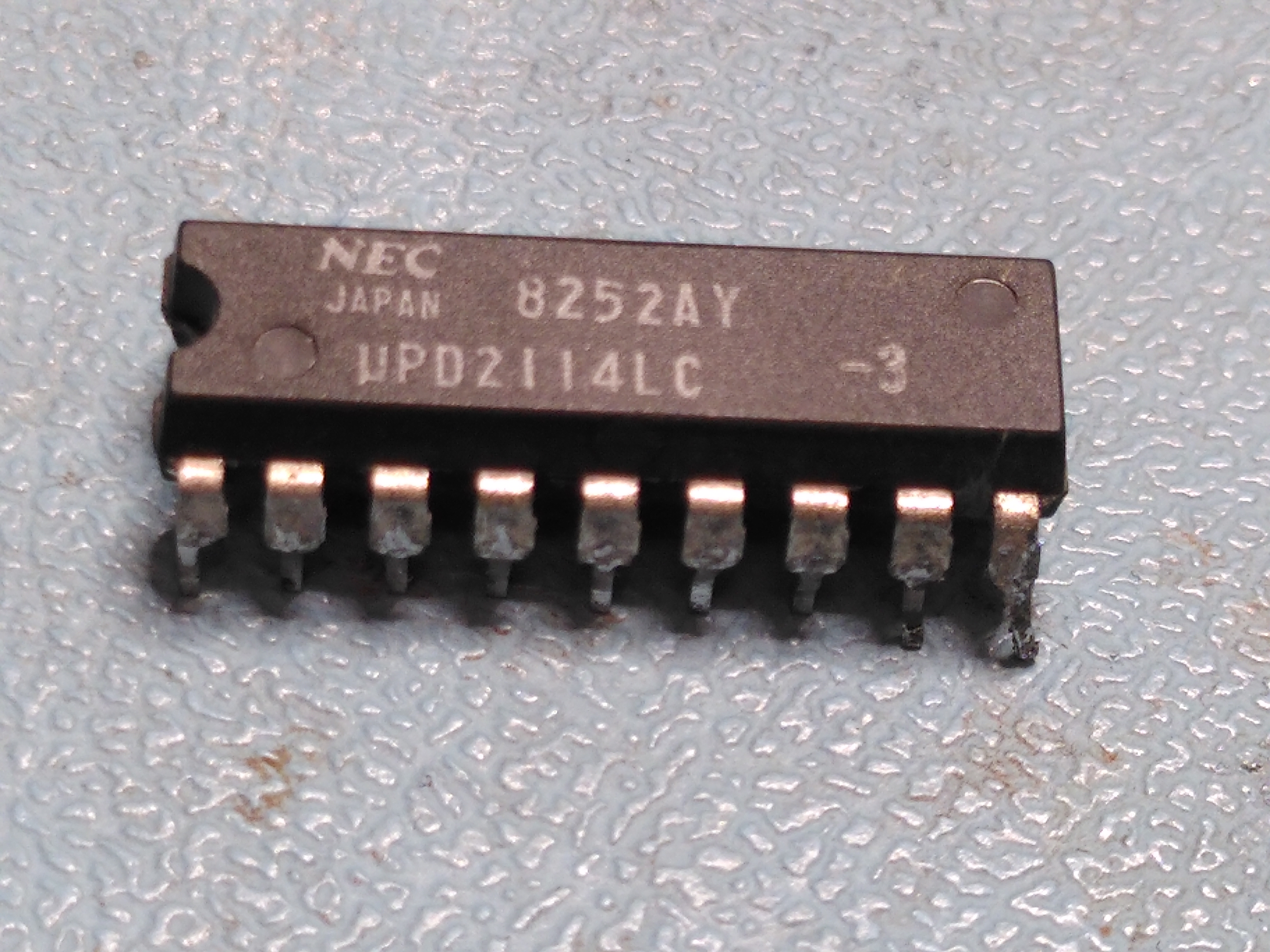
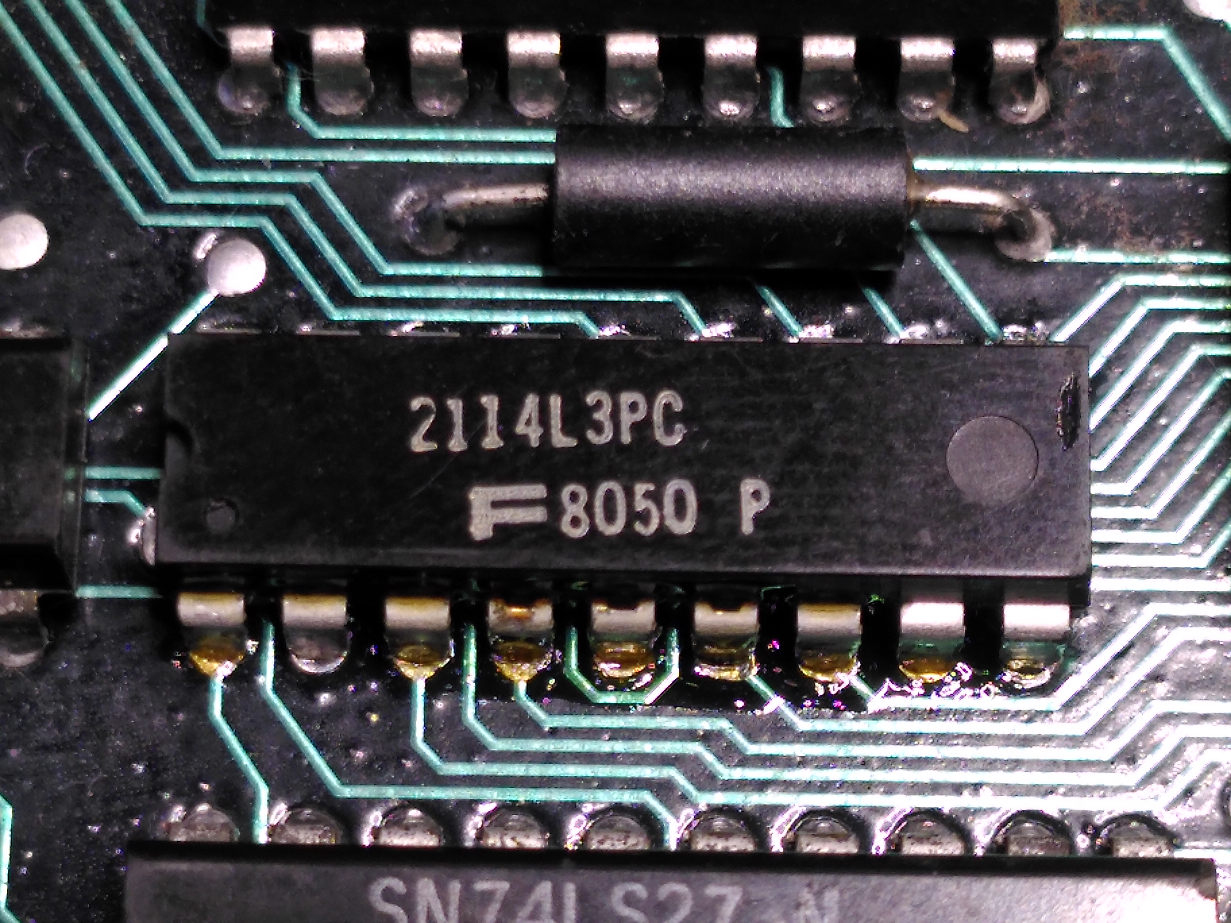
Replacing this fixed the screen display.
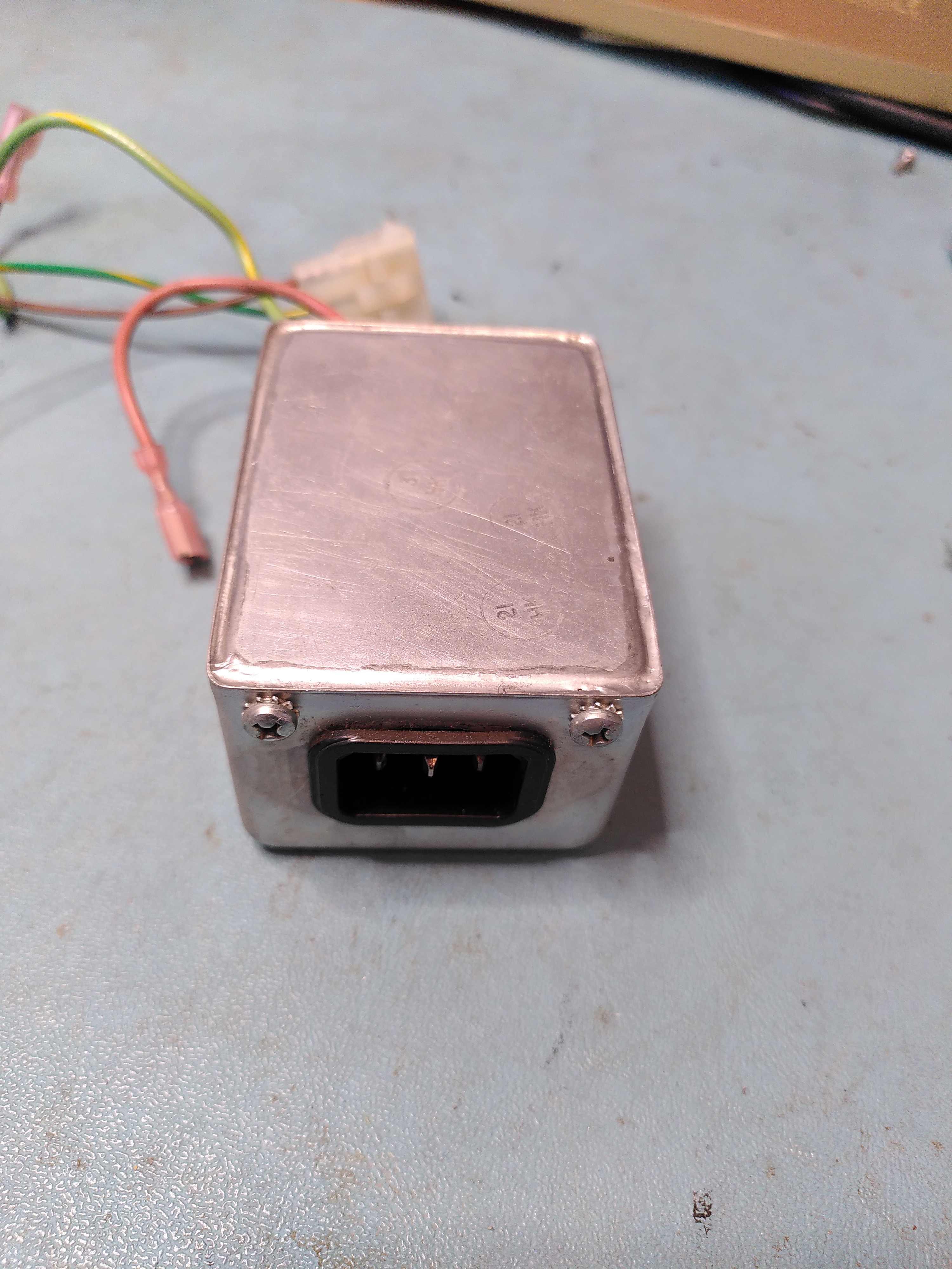
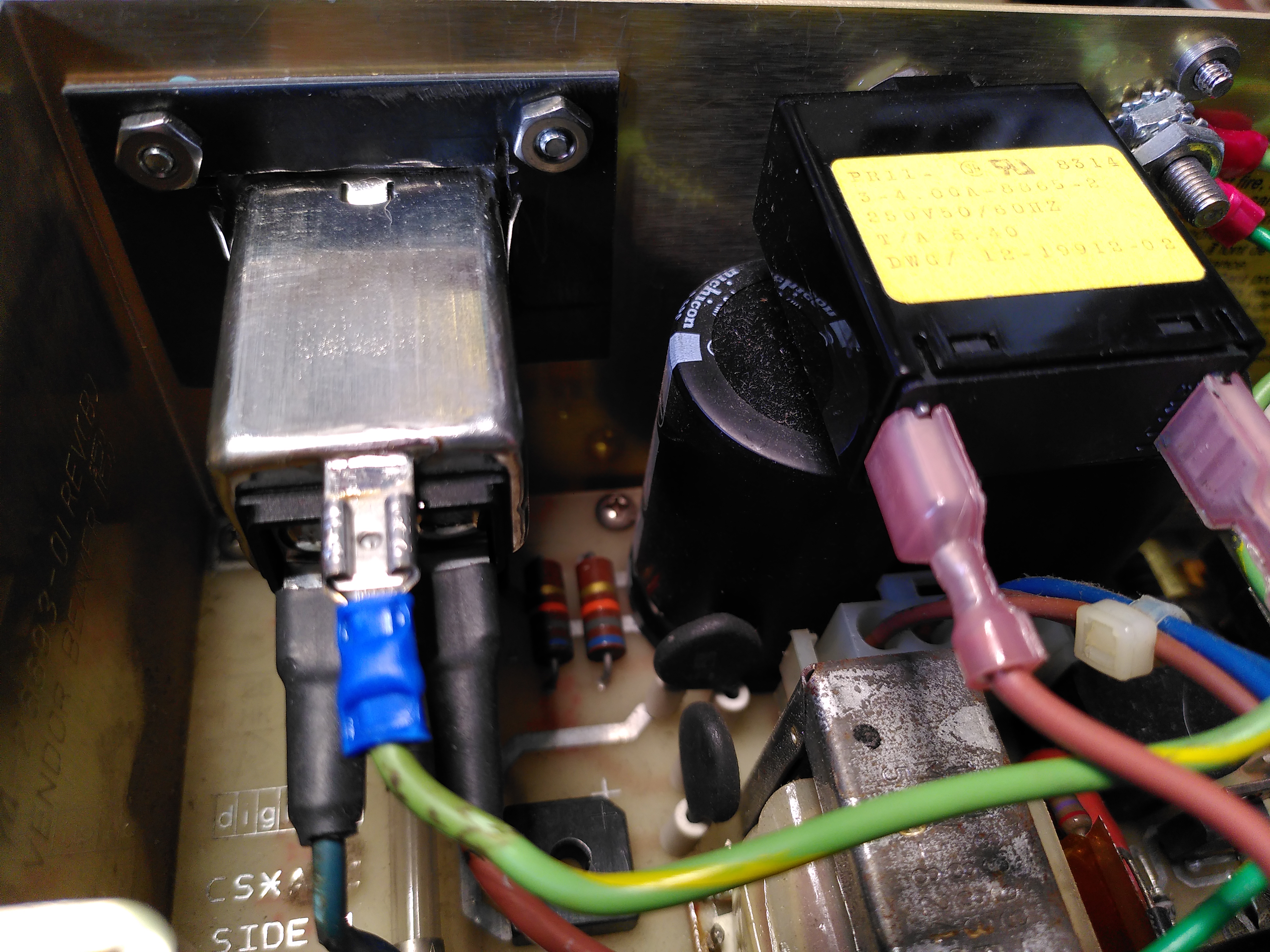
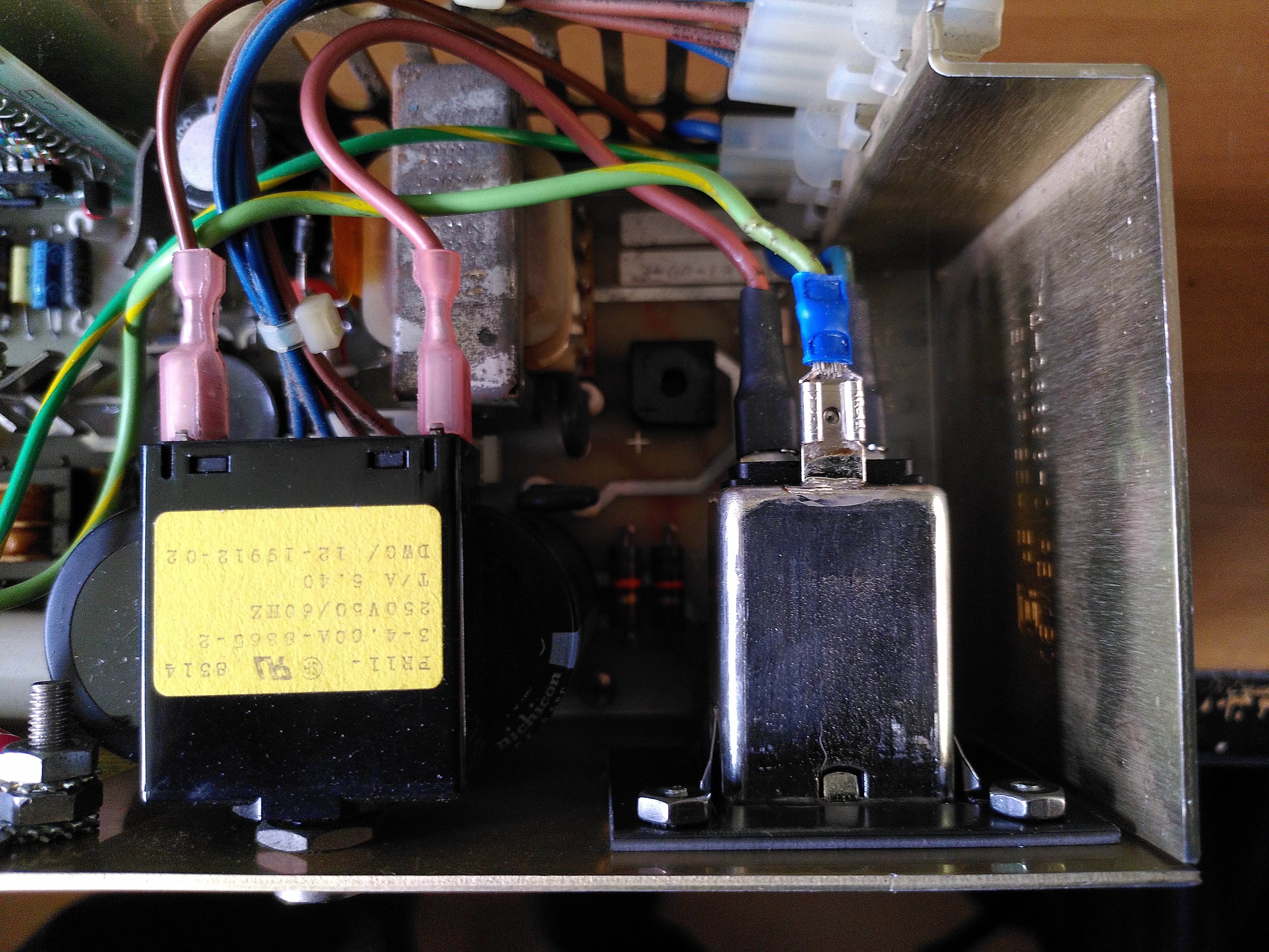
Unfortunately while diagnosing the line buffer chip fault the H7842A power supply stopped working. There was a pop when I plugged in the power cable, before the power supply was even switched on. Checking the power entry module, a Corcom F2987A, it measured a short across the inputs. I have had this happen before with one of these units.
The mounting for the power entry module is non-standard so it isn’t possible to just buy a modern replacement. I could not remember what I replaced it with when this happened before. I was advised that it is possible to open the unit and repair it, or just remove the components and not have a filter.
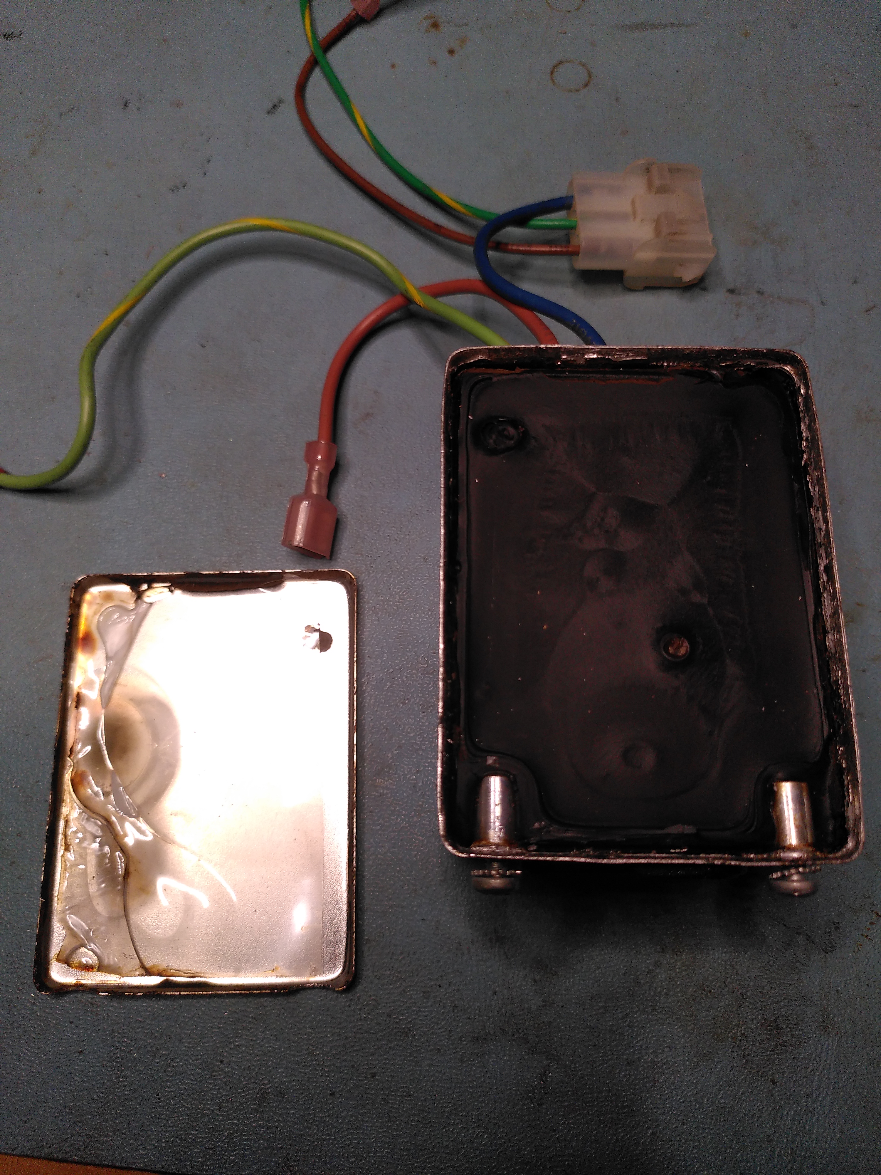
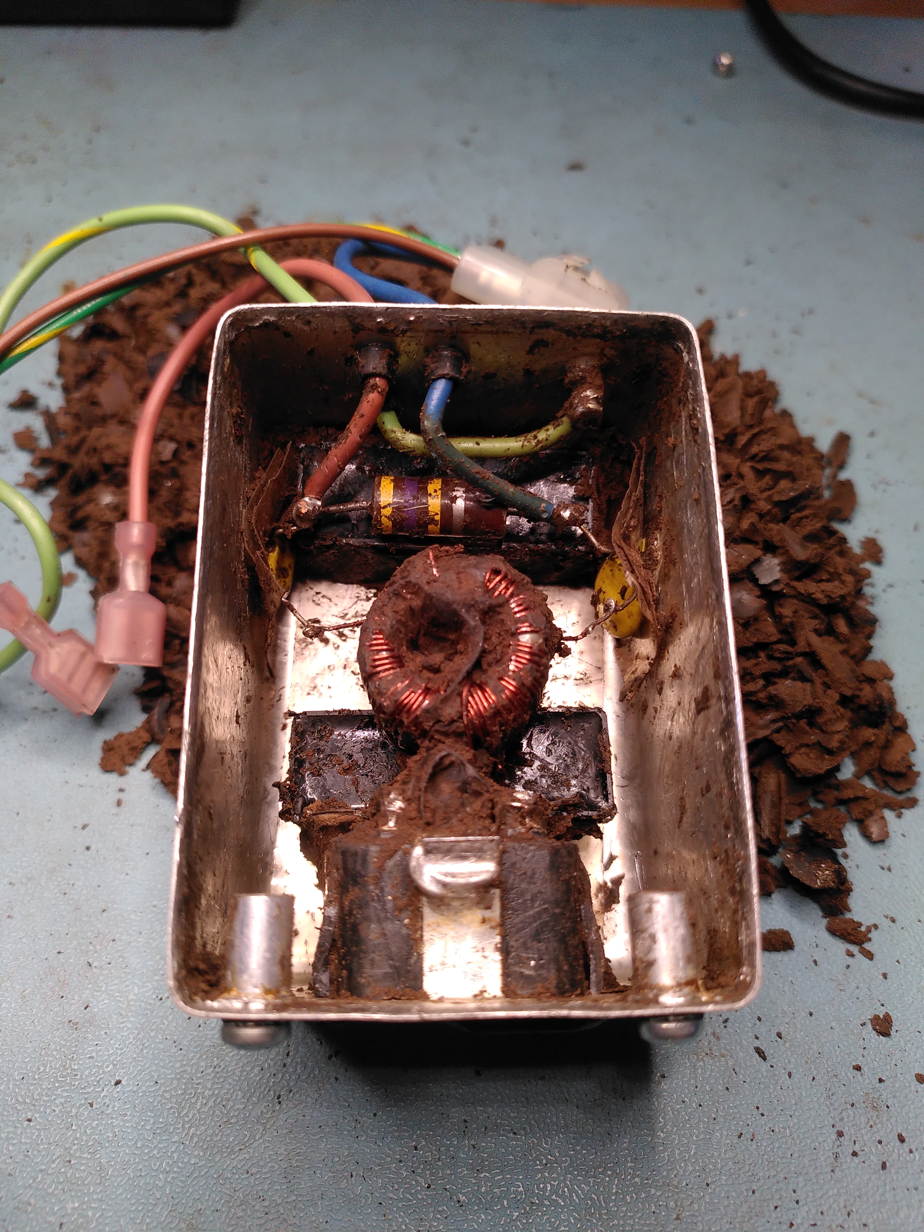
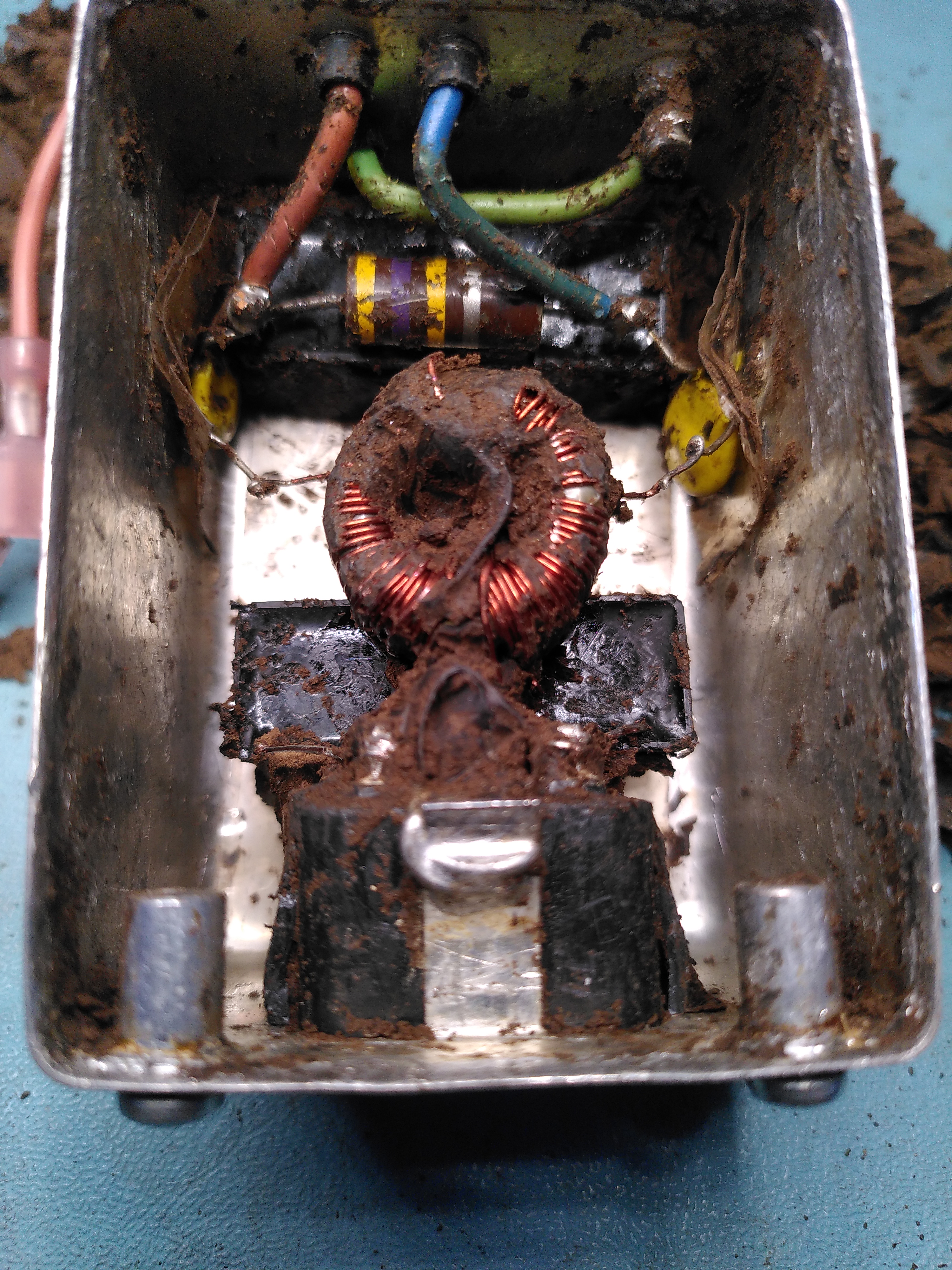
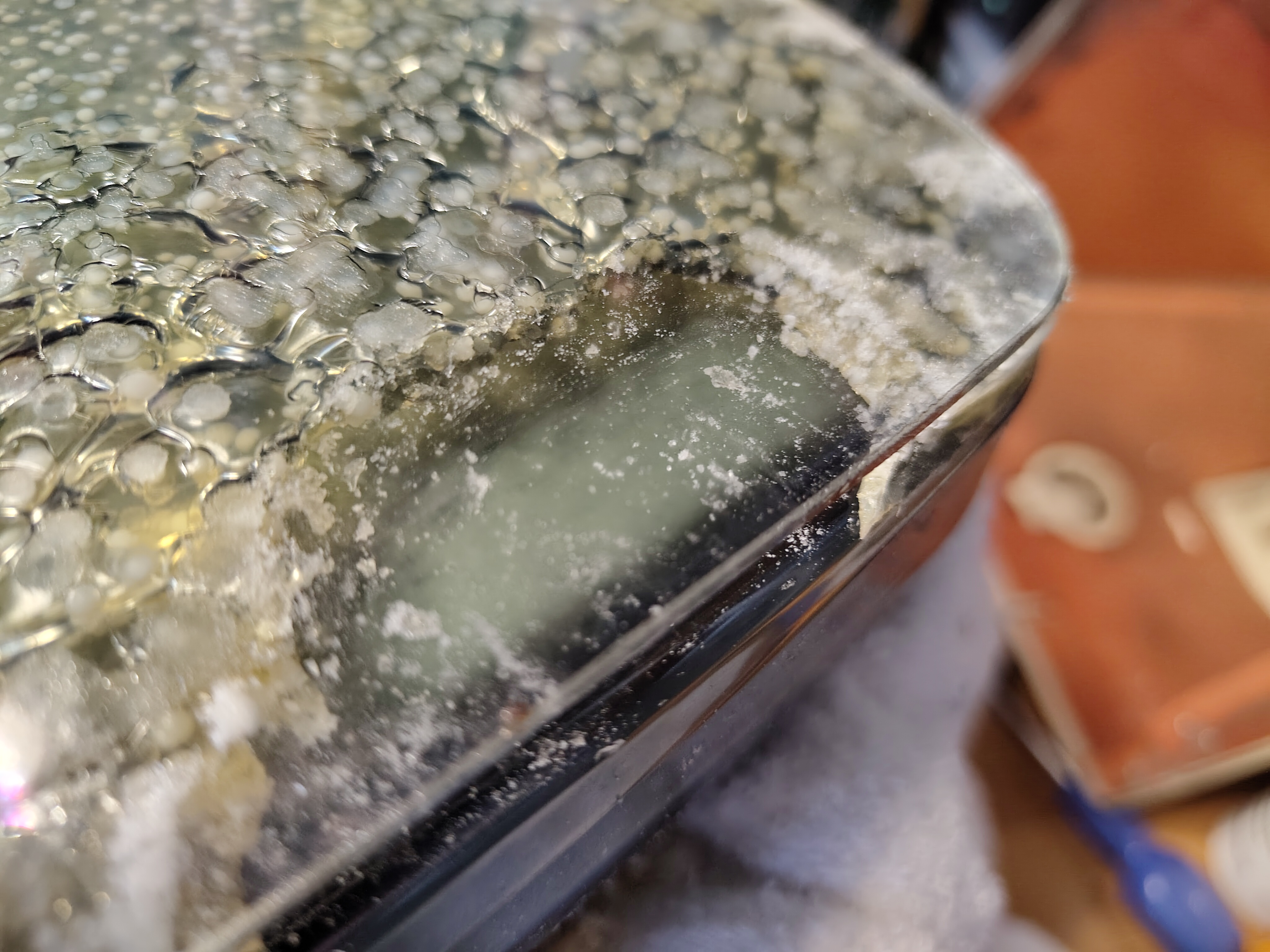
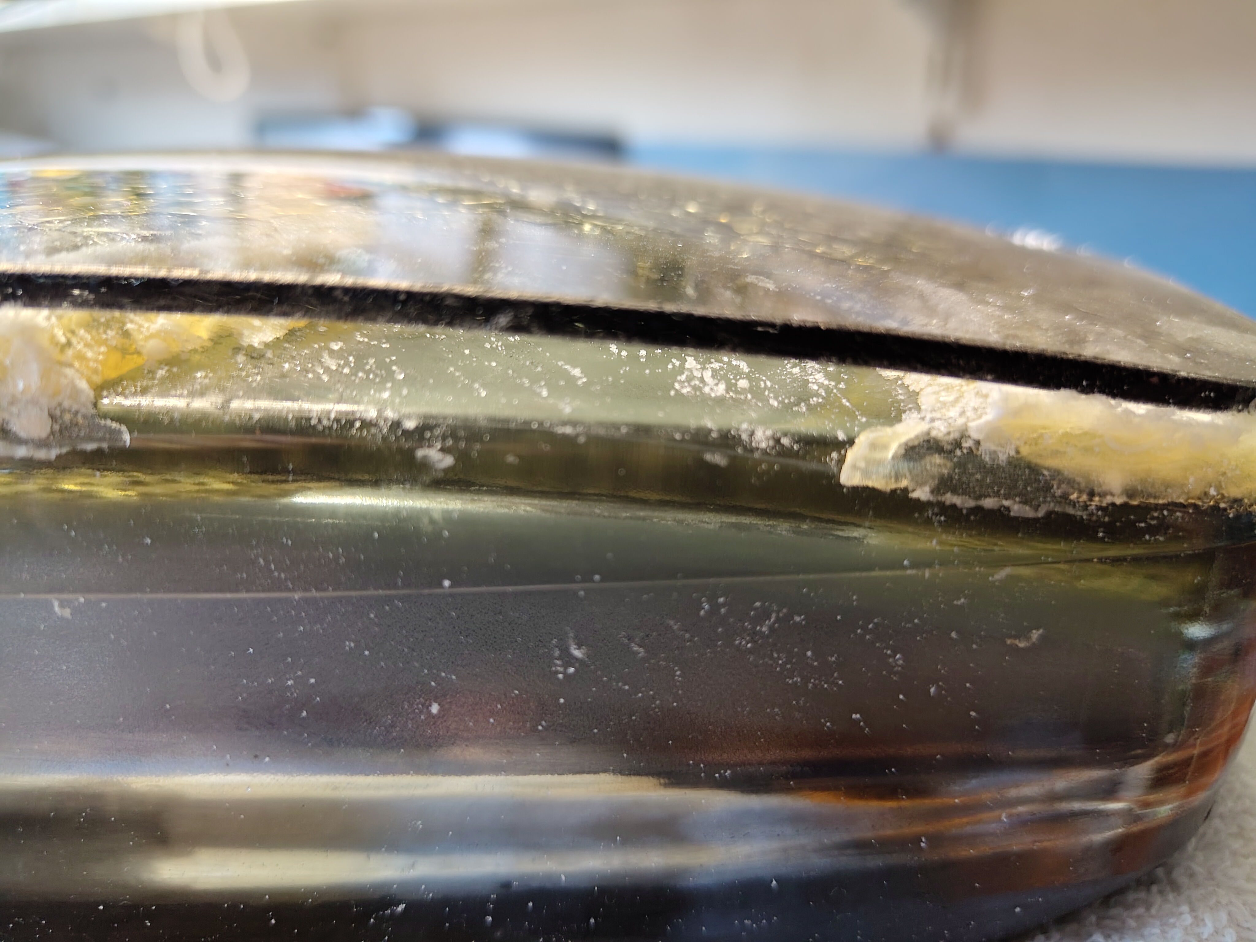
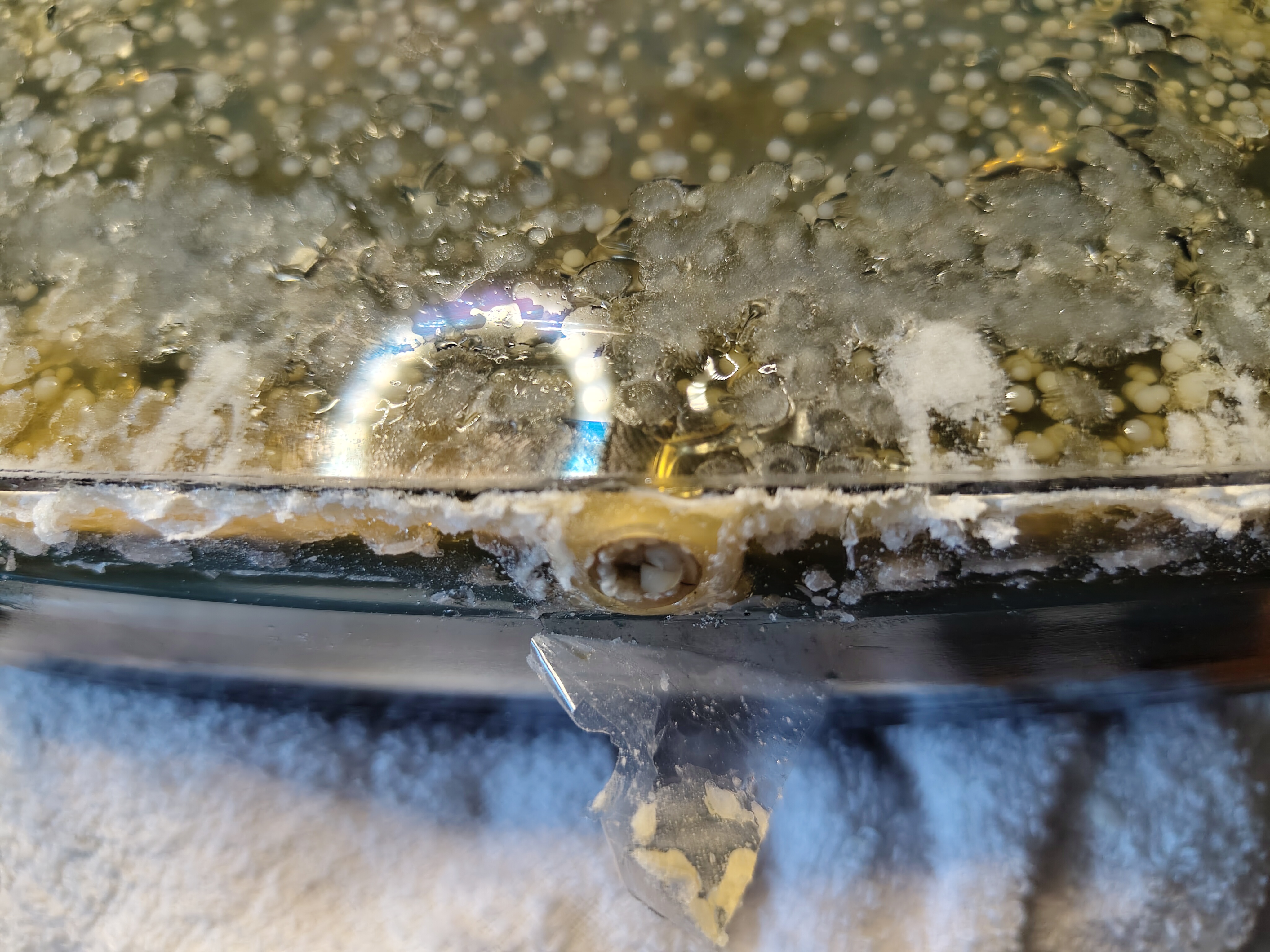
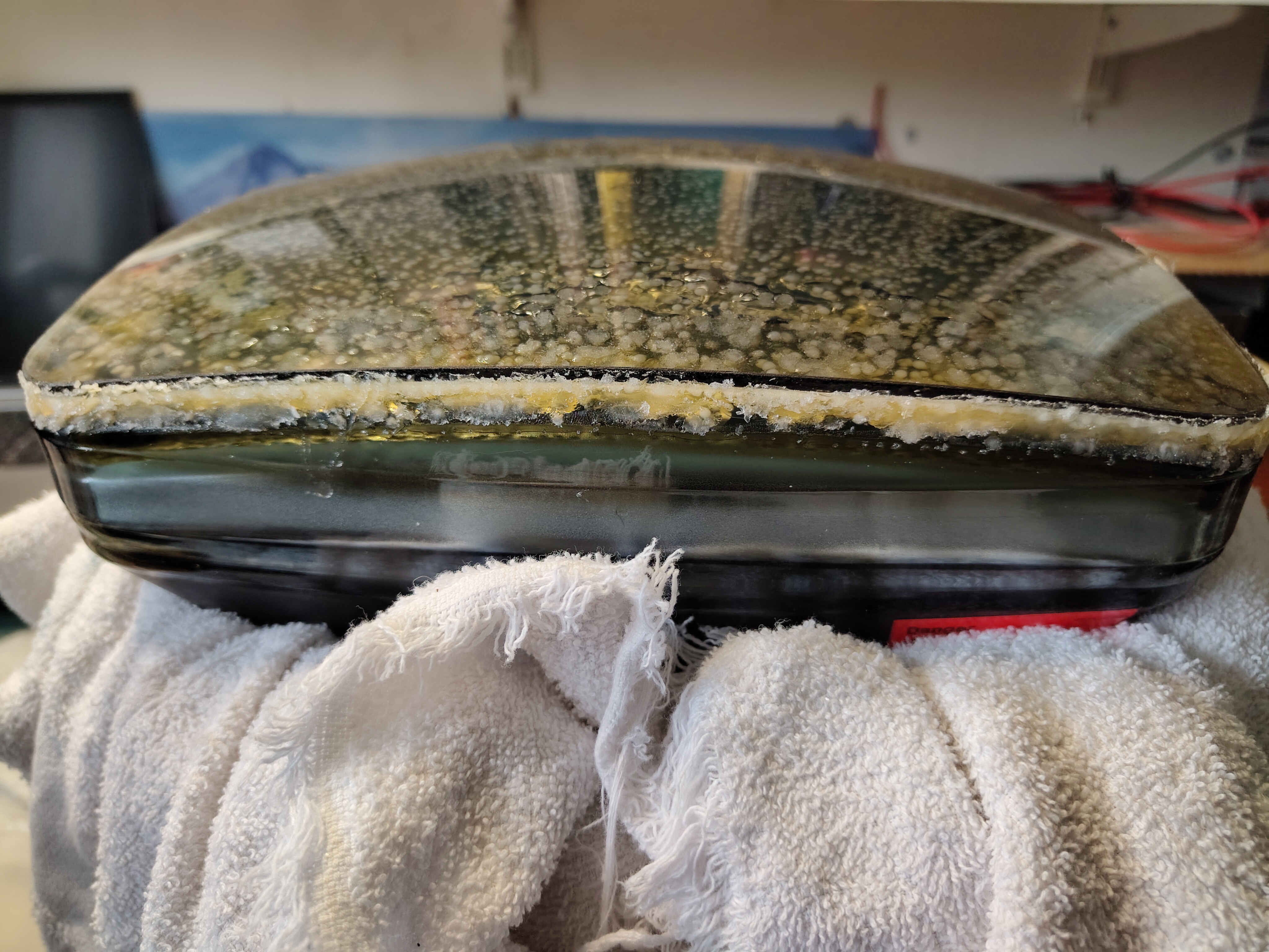
I elected to try opening it. The cover is soldered on though and being all metal it was really difficult to get enough heat to the solder to be able to open it. Eventually I managed to open it to be greeted by a huge blob of silicone.
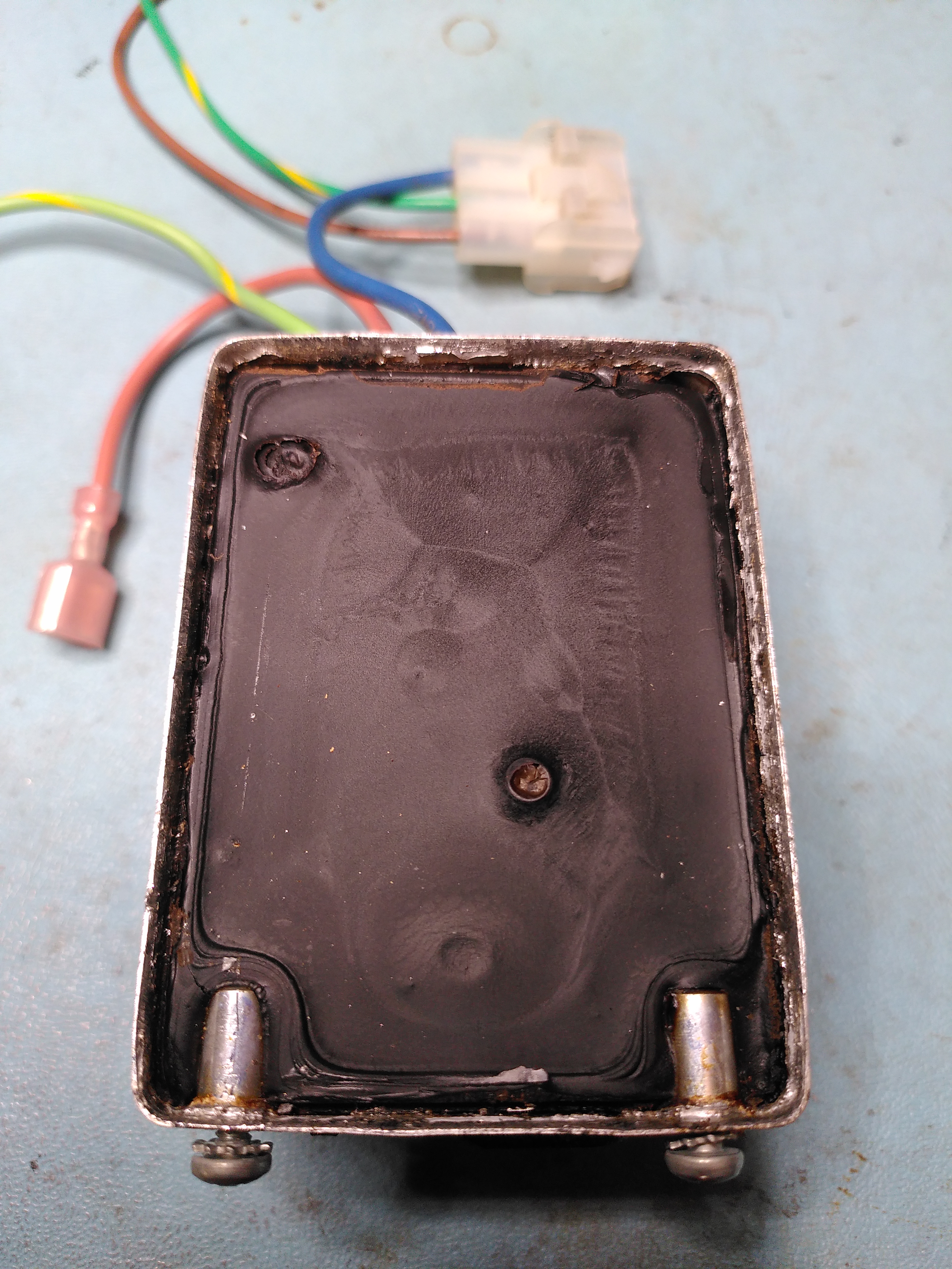
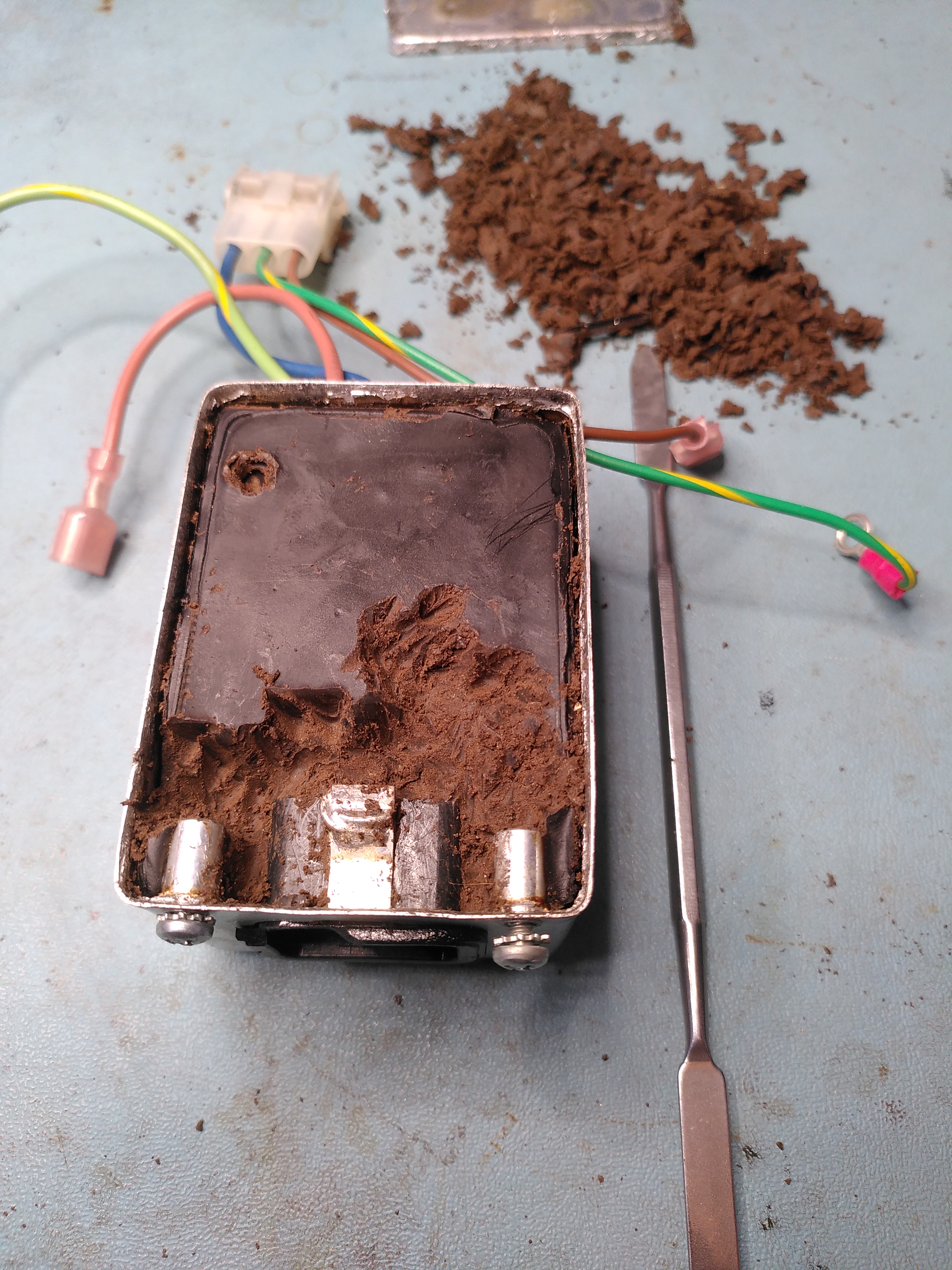
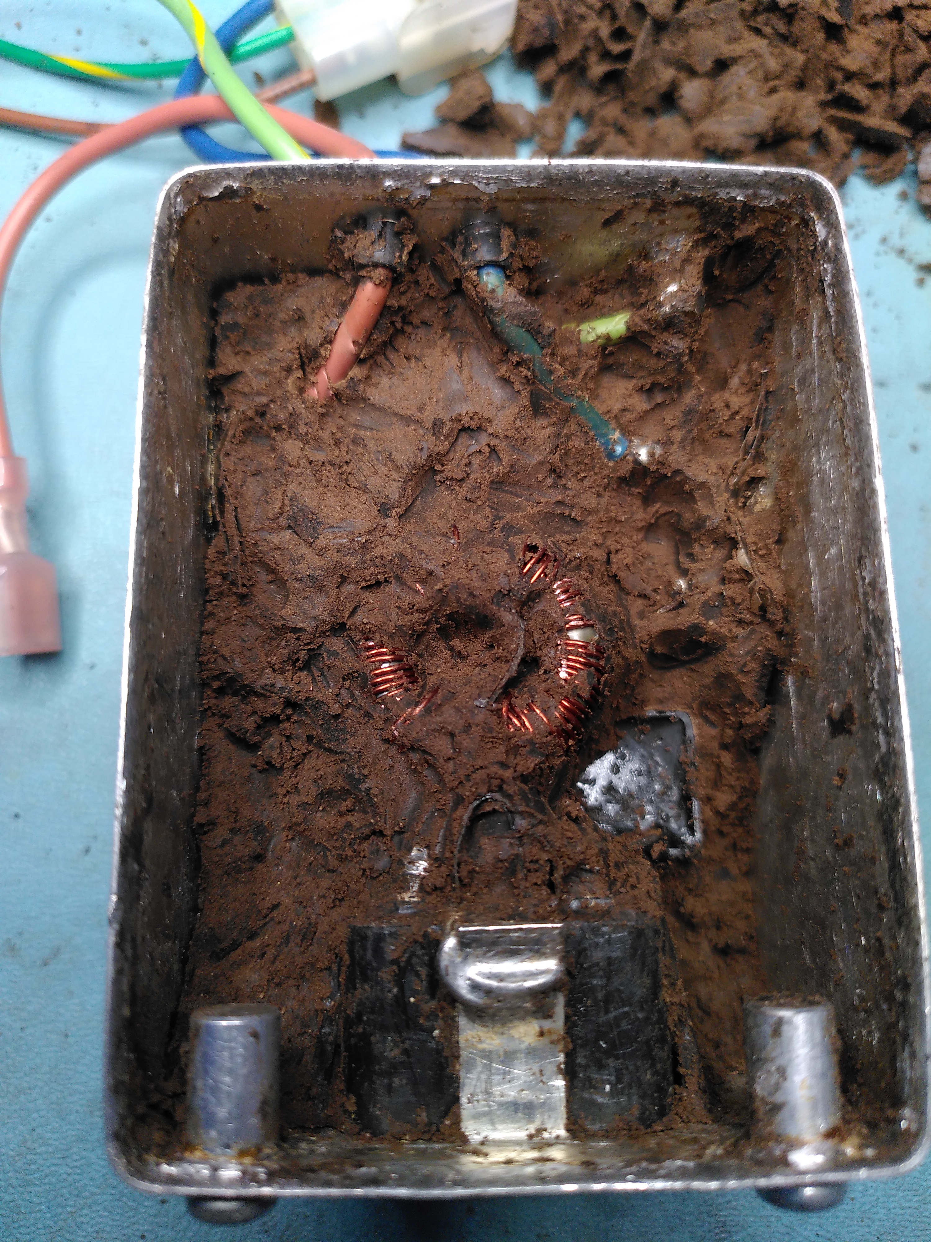
It was quite a job to excavate the components and I think I damaged the inductor in the process because one of the coils tested open circuit. I also managed to crack some of the edges on the actual inlet.

Excavating the Components in the Corcom F2987A
Excavating the Components in the Corcom F2987A
Excavating the Components in the Corcom F2987A
Excavating the Components in the Corcom F2987A
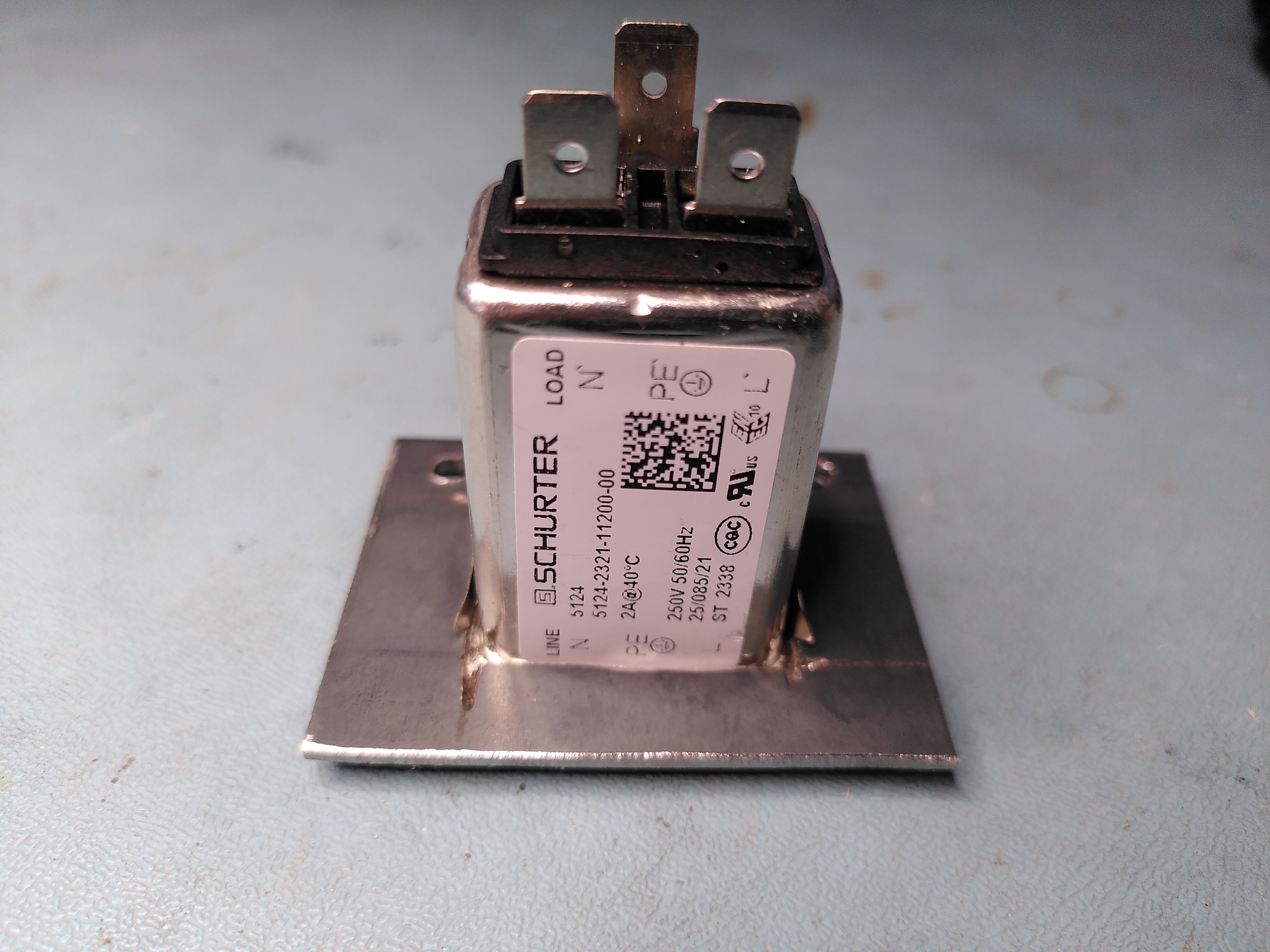
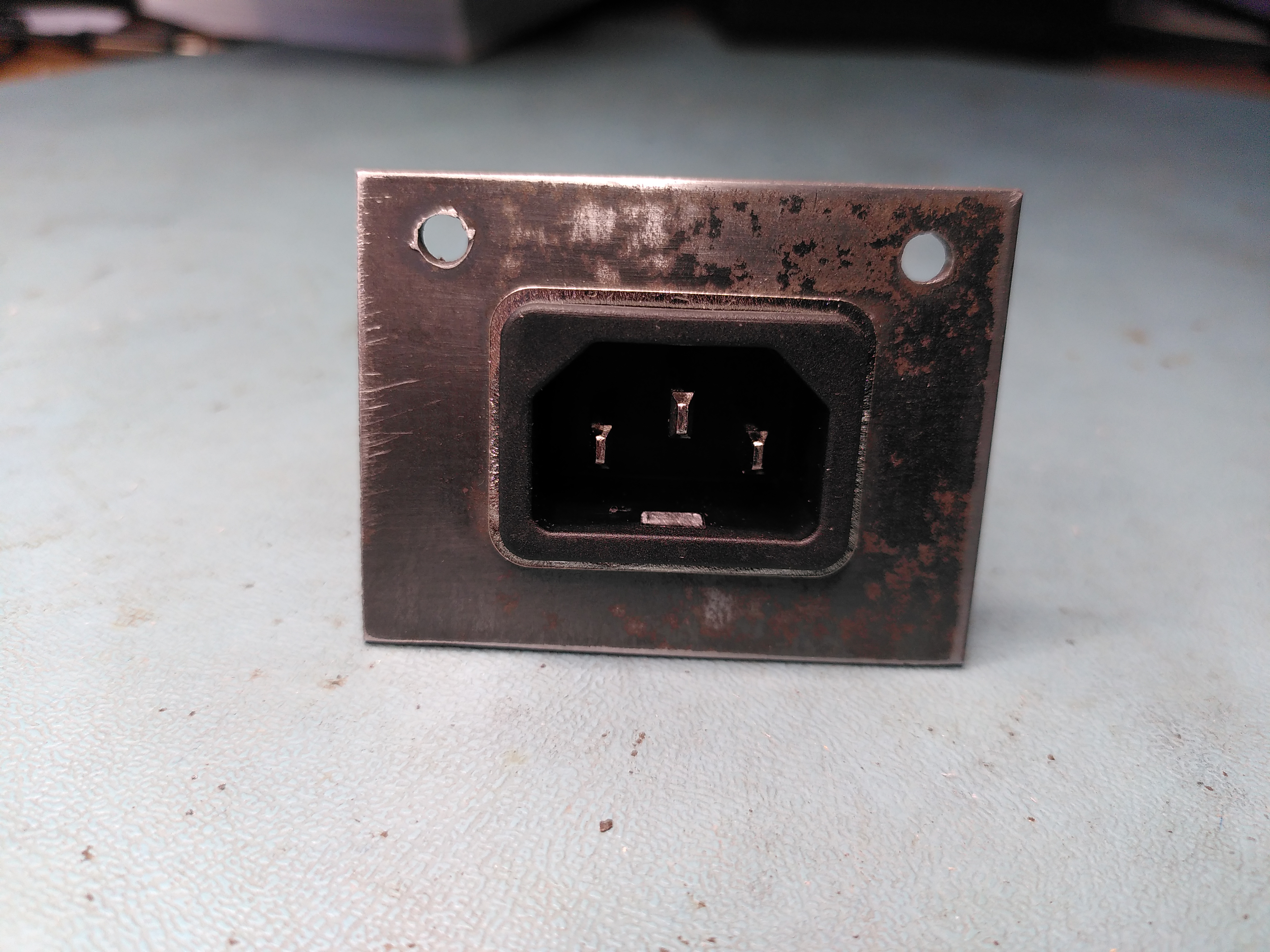
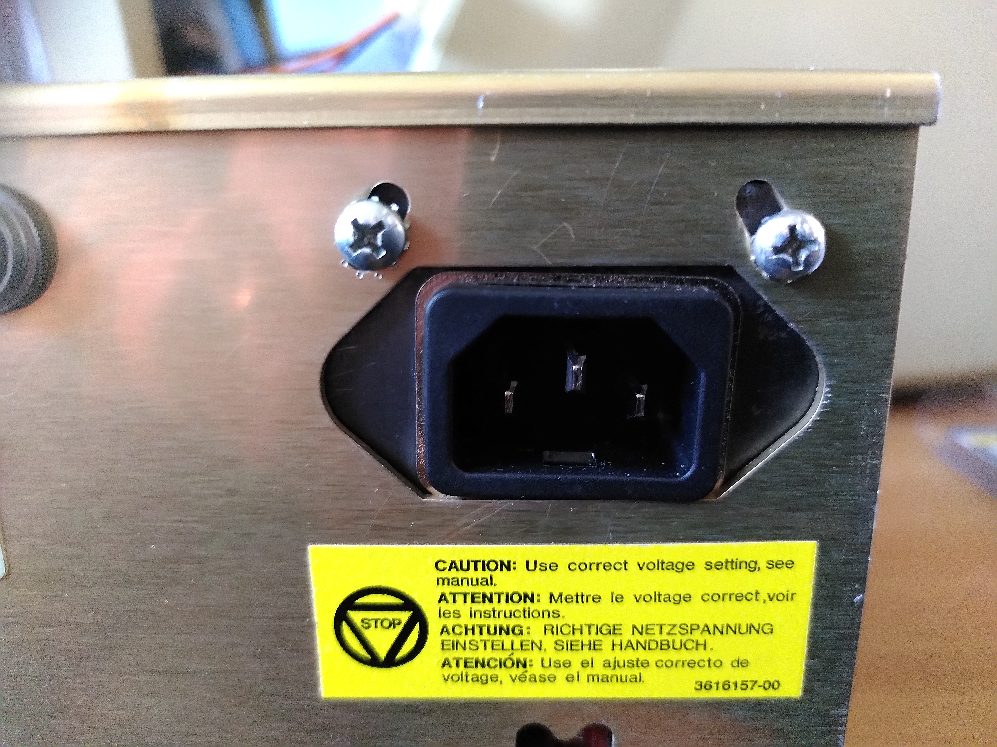
Given the damage I decided to use a modern power entry module. However I could not find any that would fit the hole in the enclosure of the original Corcom, so I got some 2mm steel and made a mounting plate in which I mounted a modern Schurter 5121 snap-in power entry module.
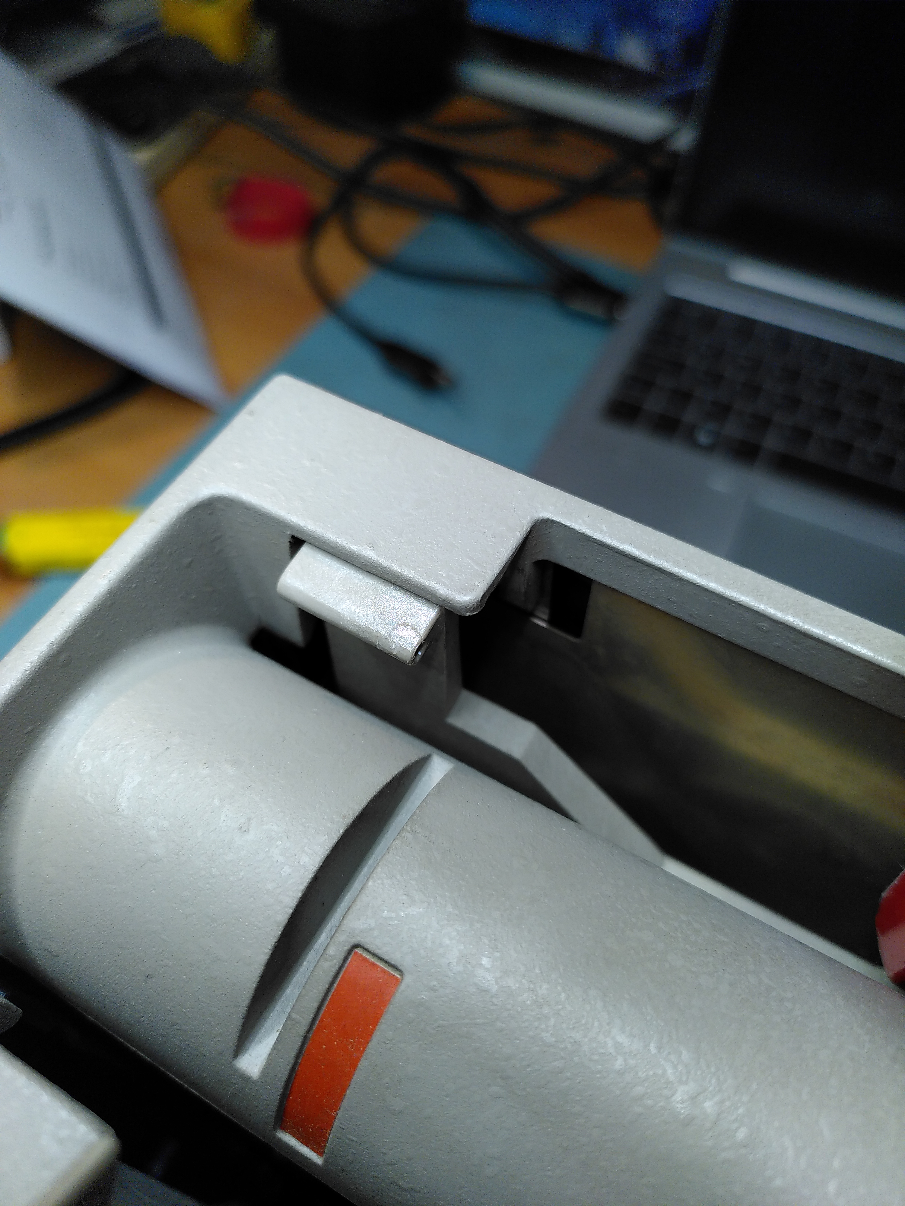
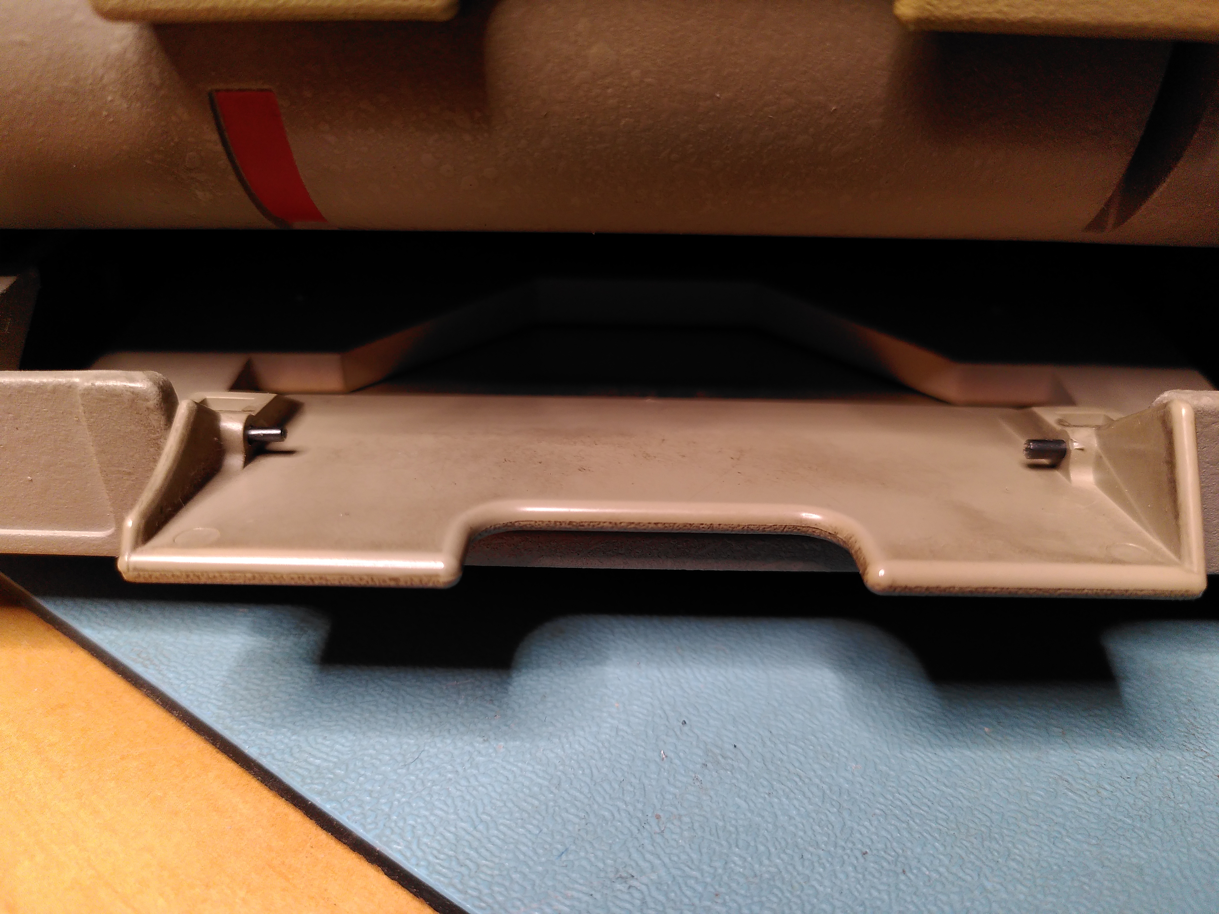
RX50 Floppy Disk Drive Door
The RX50 floppy disk drive had one of its doors adrift. The pins holding it in have been lost and one of the mounting holds was a little damaged. I glued back the damaged plastic to repair the mounting hole using ProWeld.
I didn’t know where to get new mounting pins so I found something similar on eBay. Although not being polished they are stiffer. The new pins were slightly too big, but thankfully their design allowed me to reduce the diameter and I was able to fit them.
The door is now back on, although a little stiffer.
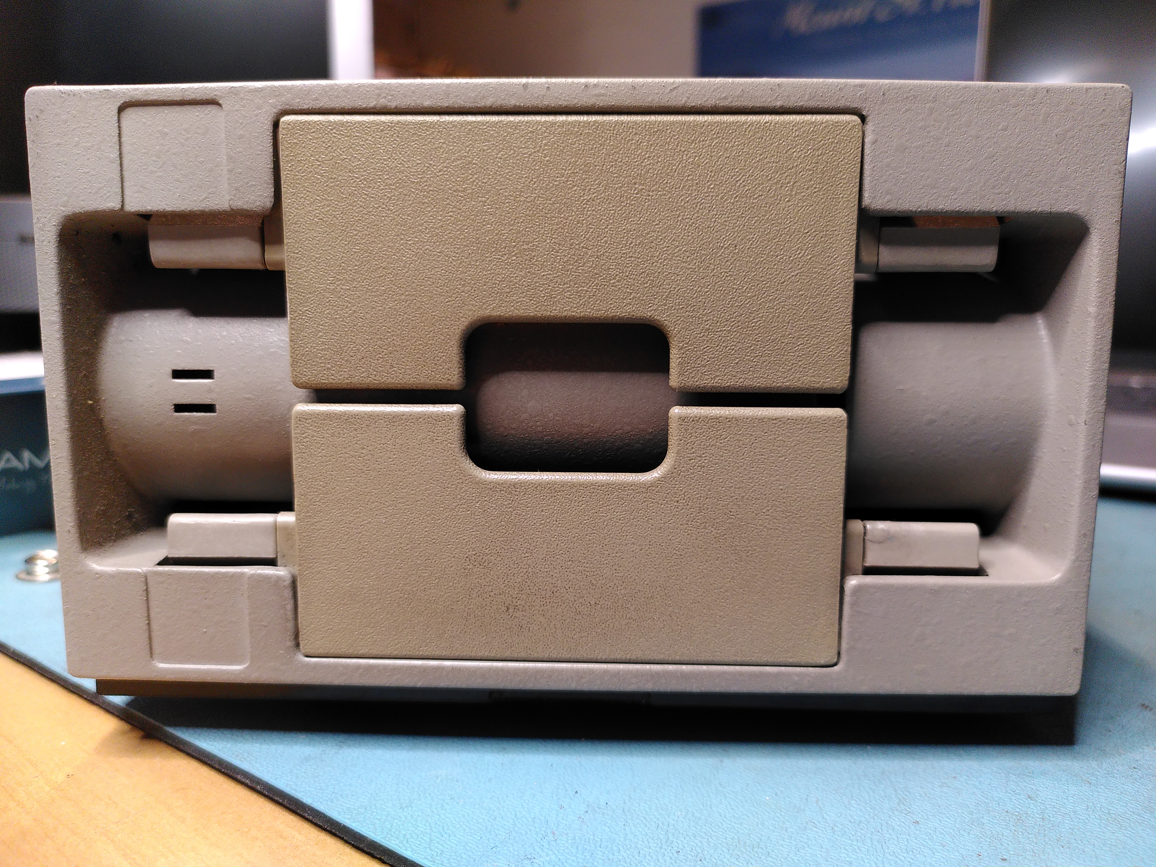
RX50 Not Reading Disks
During my work on trying to restore this machine I also found that the RX50 would not read any disks. By comparing with a known good RX50 it didn’t take long to realise that it was not spinning the disks. On startup it runs both the head stepper motor and the spindle motor. But the spindle was not rotating.
On closer inspection I found that it was trying to turn the spindle but it just twitched slightly. I found that the spindle was quite hard to turn by hand, certainly compared to the known good RX50. I started to take it apart a bit and after the cone lift covers came off the spindle moved more freely.
I did a few checks and this seemed to be the problem. Reassembling the drive fixed the issue. I suspect that one of the cone lift covers was not correctly aligned. Possibly as a result of whatever had damaged the door, or possibly as a result of my attempts to fix the door. Whatever the cause the RX50 now works.
I also managed to damage the cable slightly because it is close to a sharp corner on the PSU and it is easy to crush the wires. The damage seems intermittent, but clearly the cable is not in good condition.
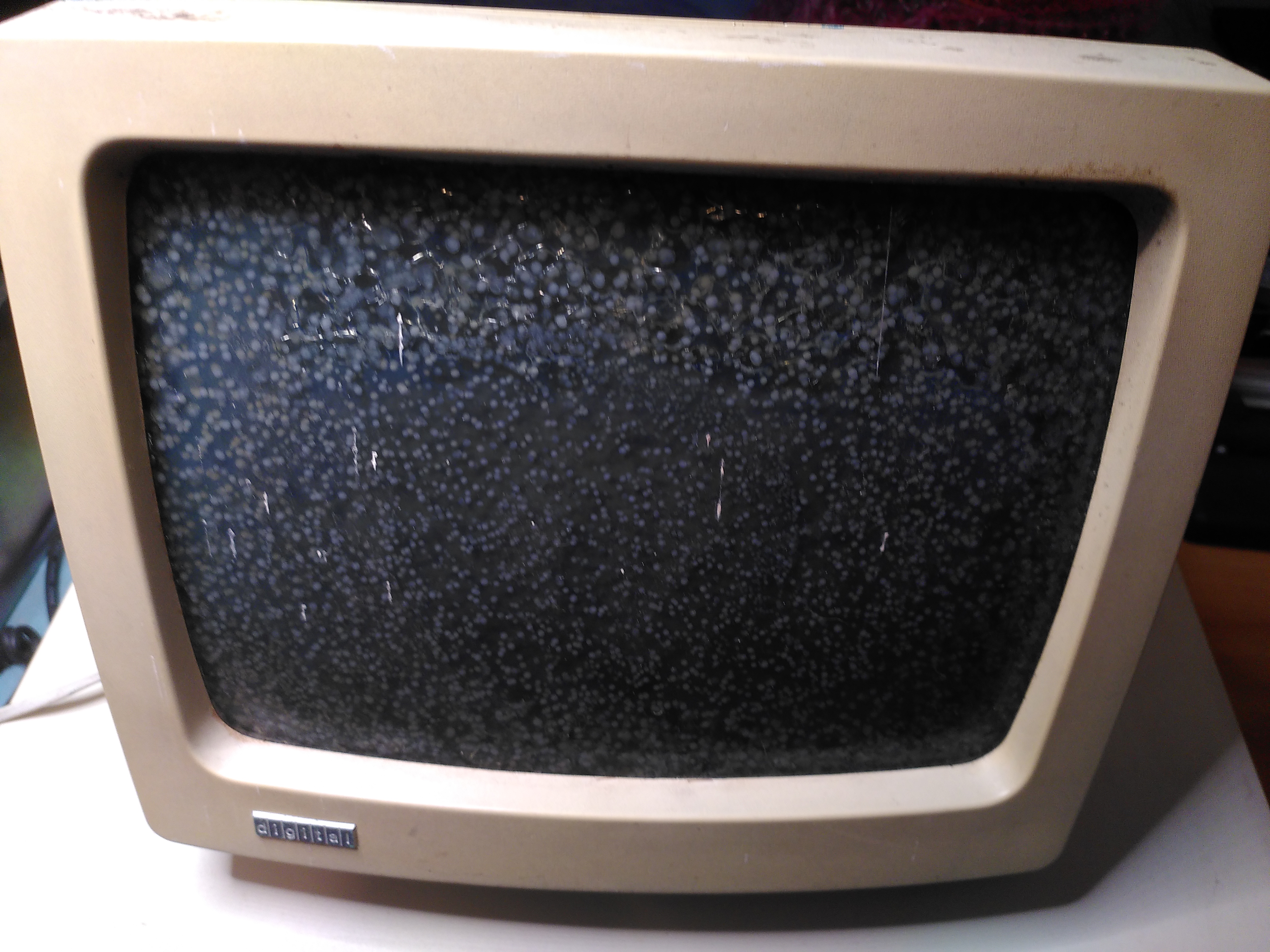
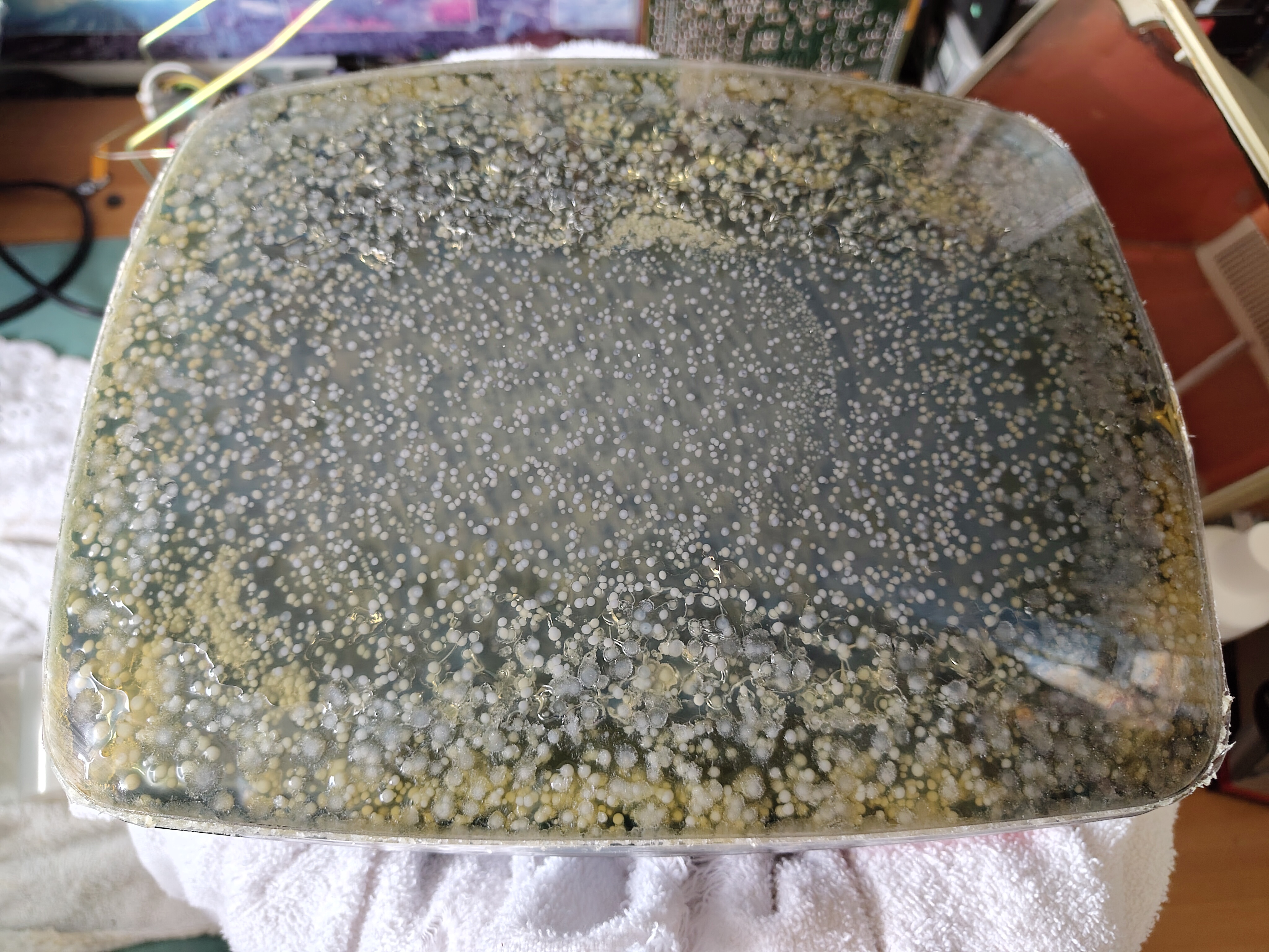
Screen Cataracts
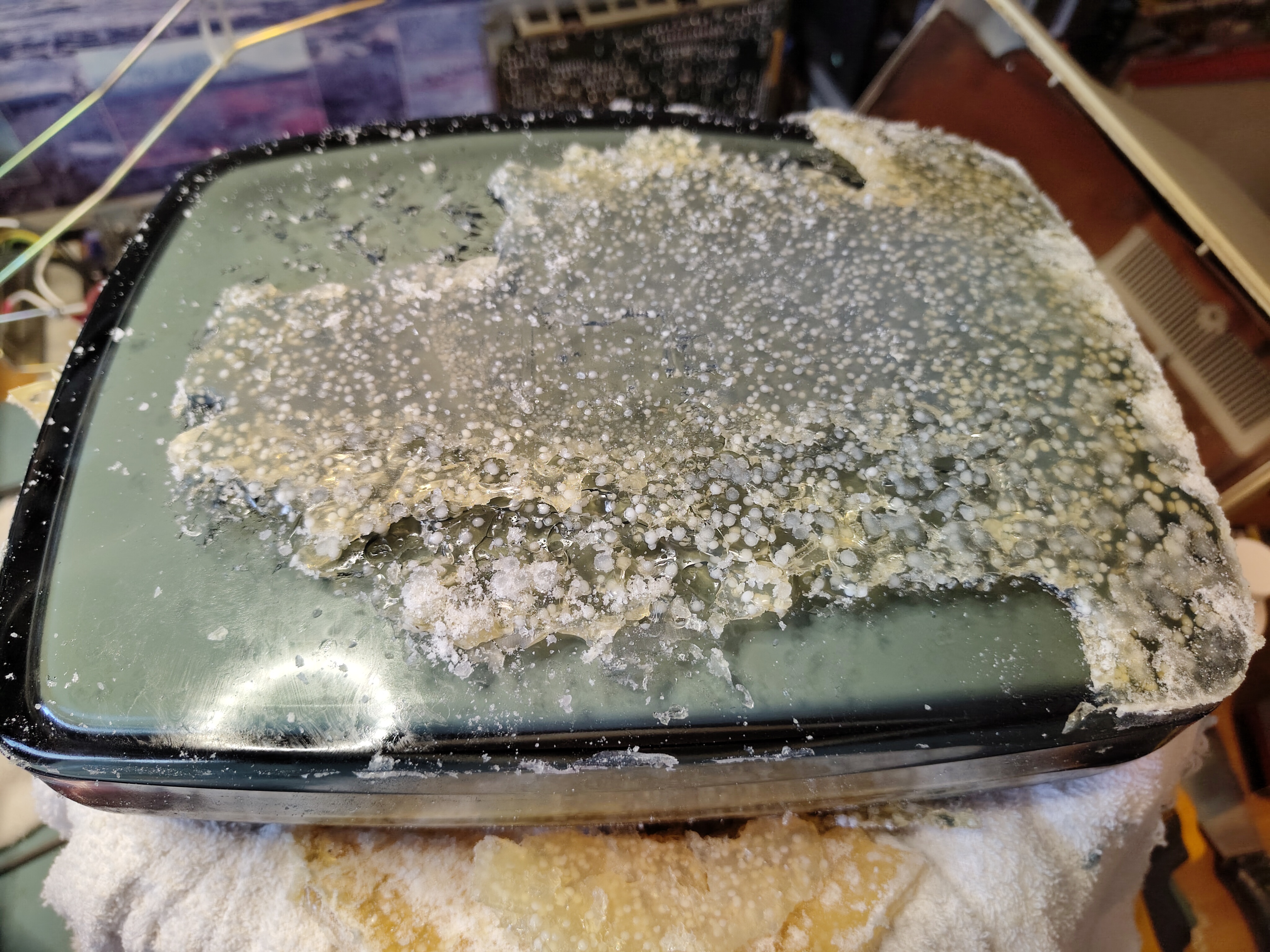
The VR201 had some pretty bad cataracts when I collected the machine, but it does appear to work.
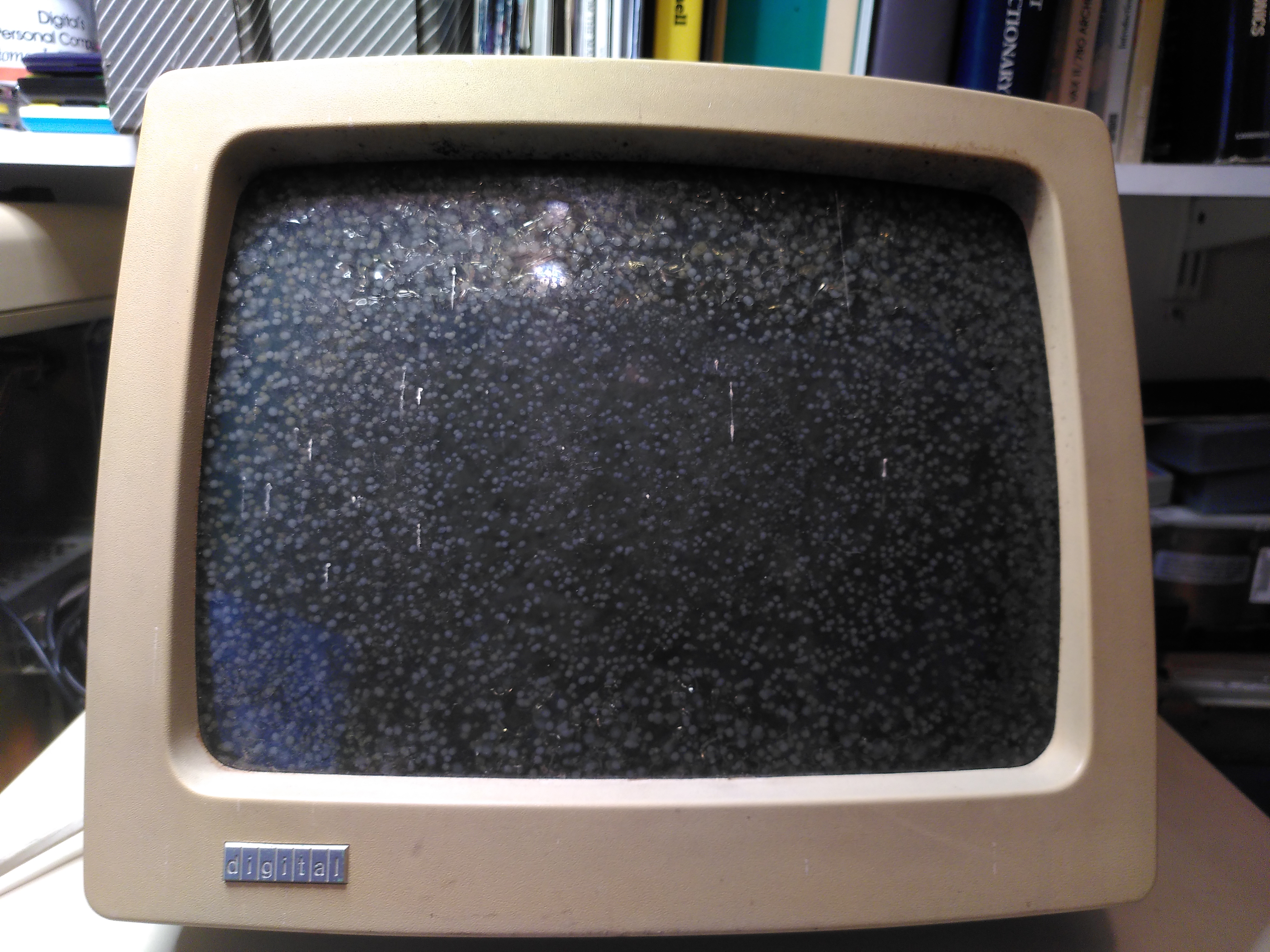
Fixing cataracts is not something I have done before. I followed this guidance from the VCF Forums and this too, in particular for dismantling the VR201. Removing the cover showed the interior to be very clean.
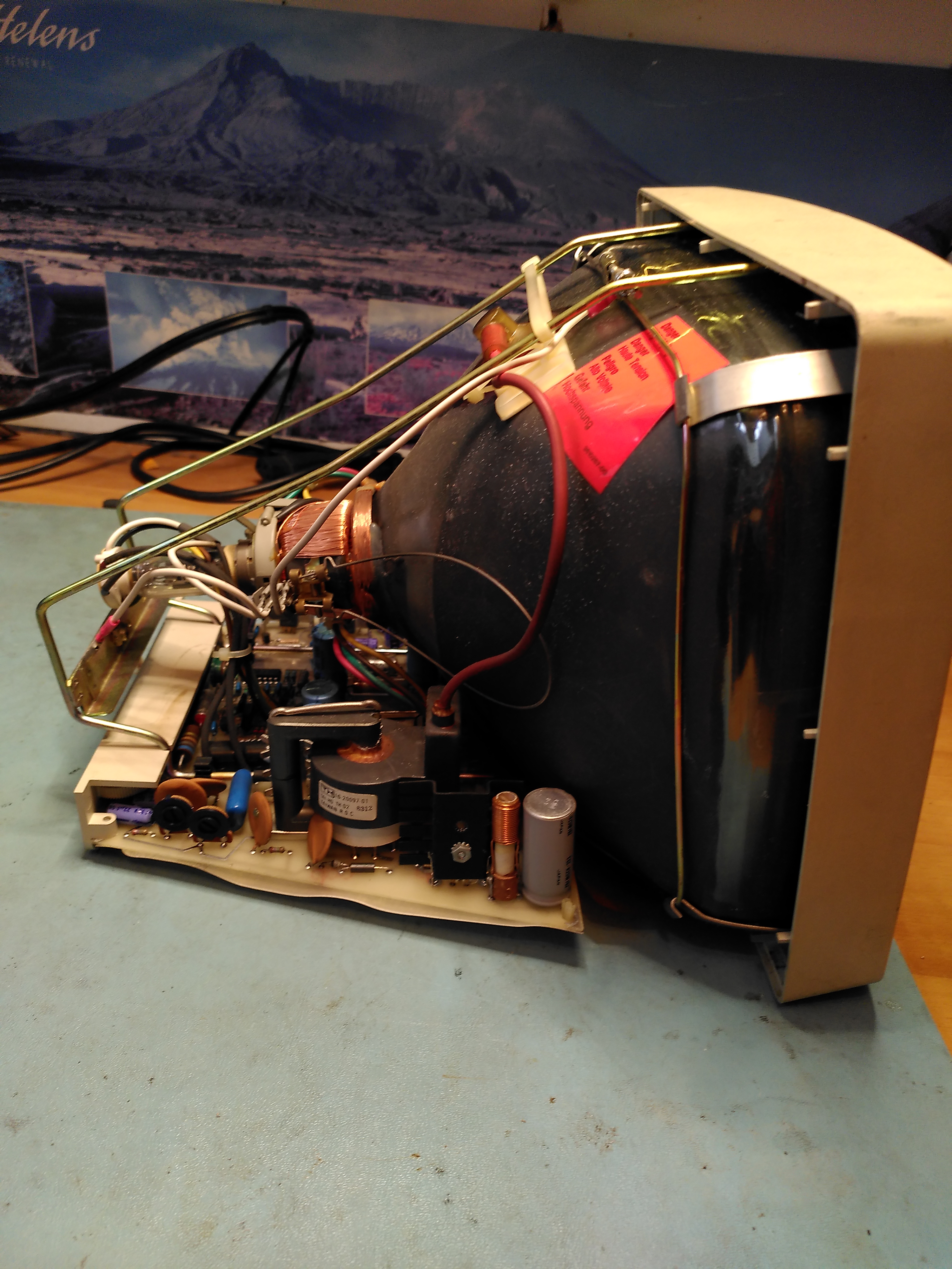
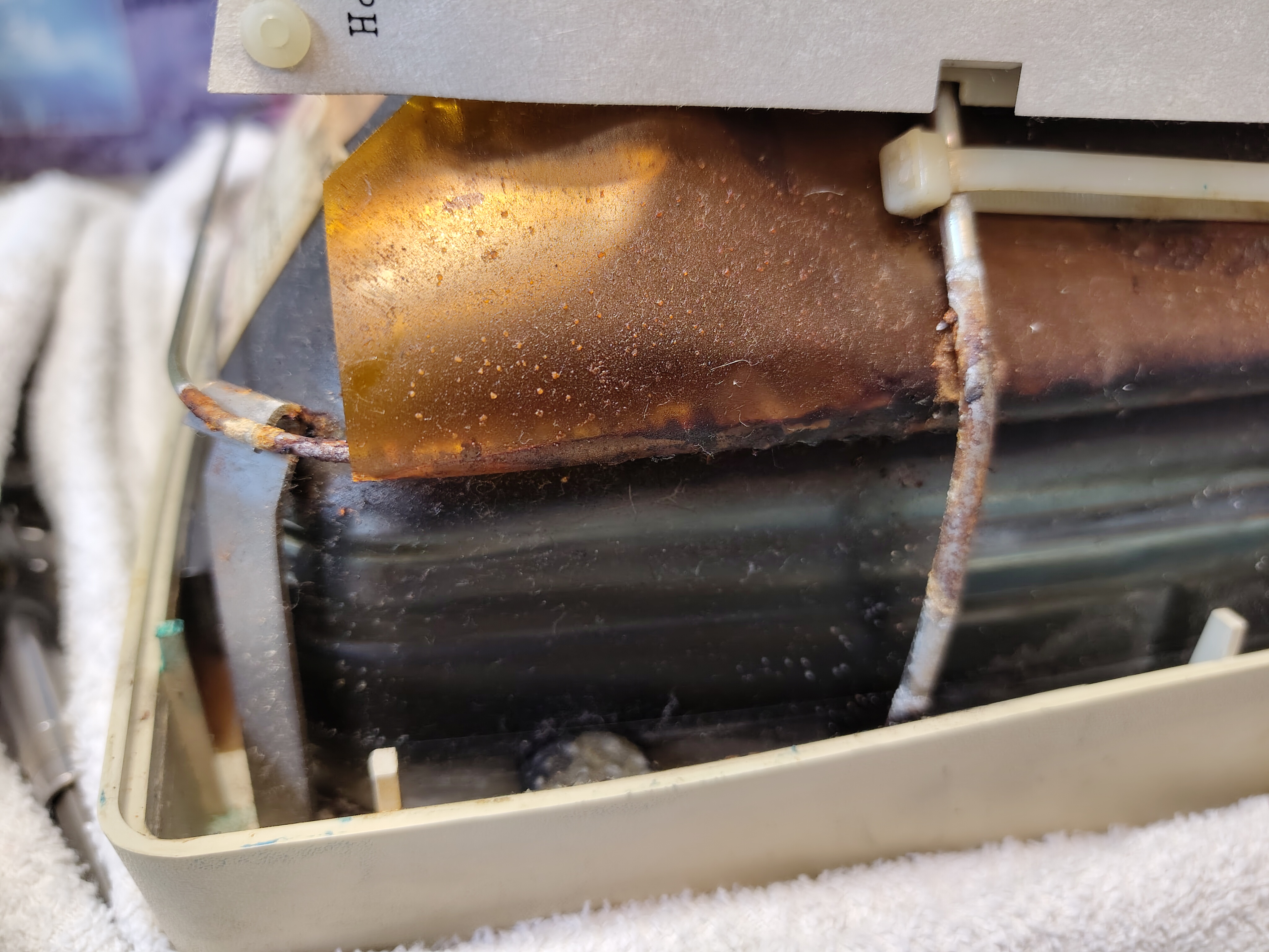
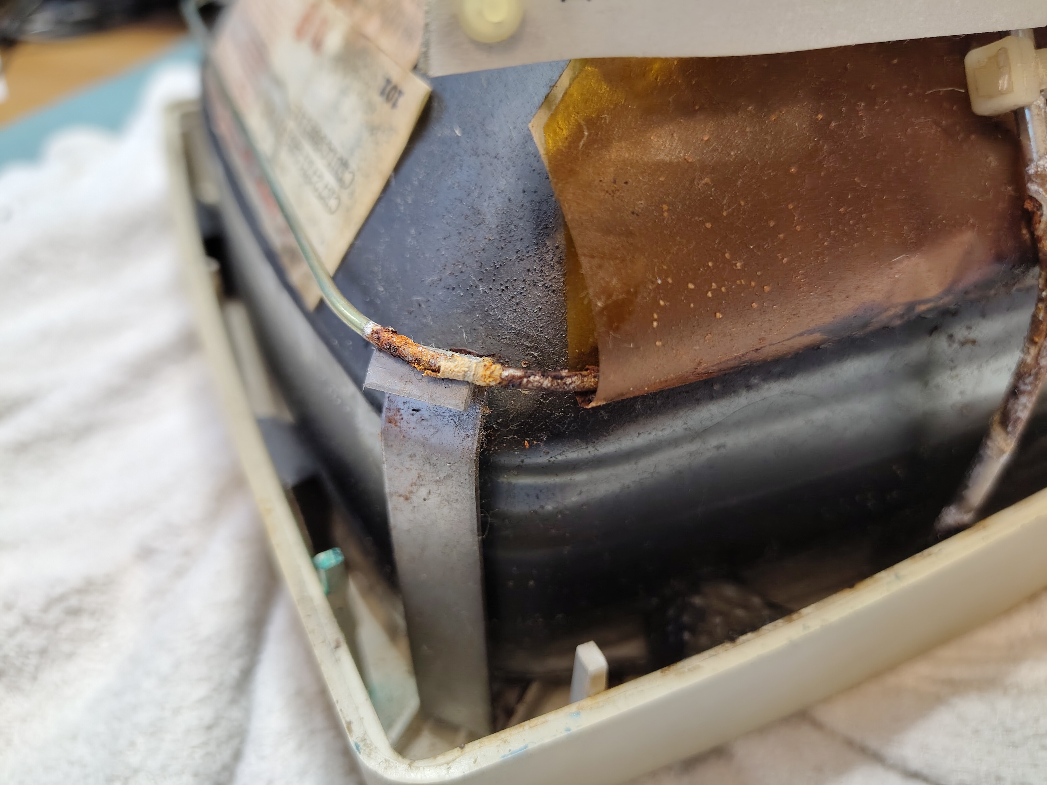
I made sure the anode cap was discharged first. Then I removed the brace that attaches the CRT to the bezel and the cables connecting to the tube. I found what looked like a rusty gunge in parts of the brace and what looked like a bit of mild corrosion. I am not sure what the gunge was, but VCF forum posts suggest it is PVA and corrosive, however, once I had removed it the corrosion didn’t seem to bad.
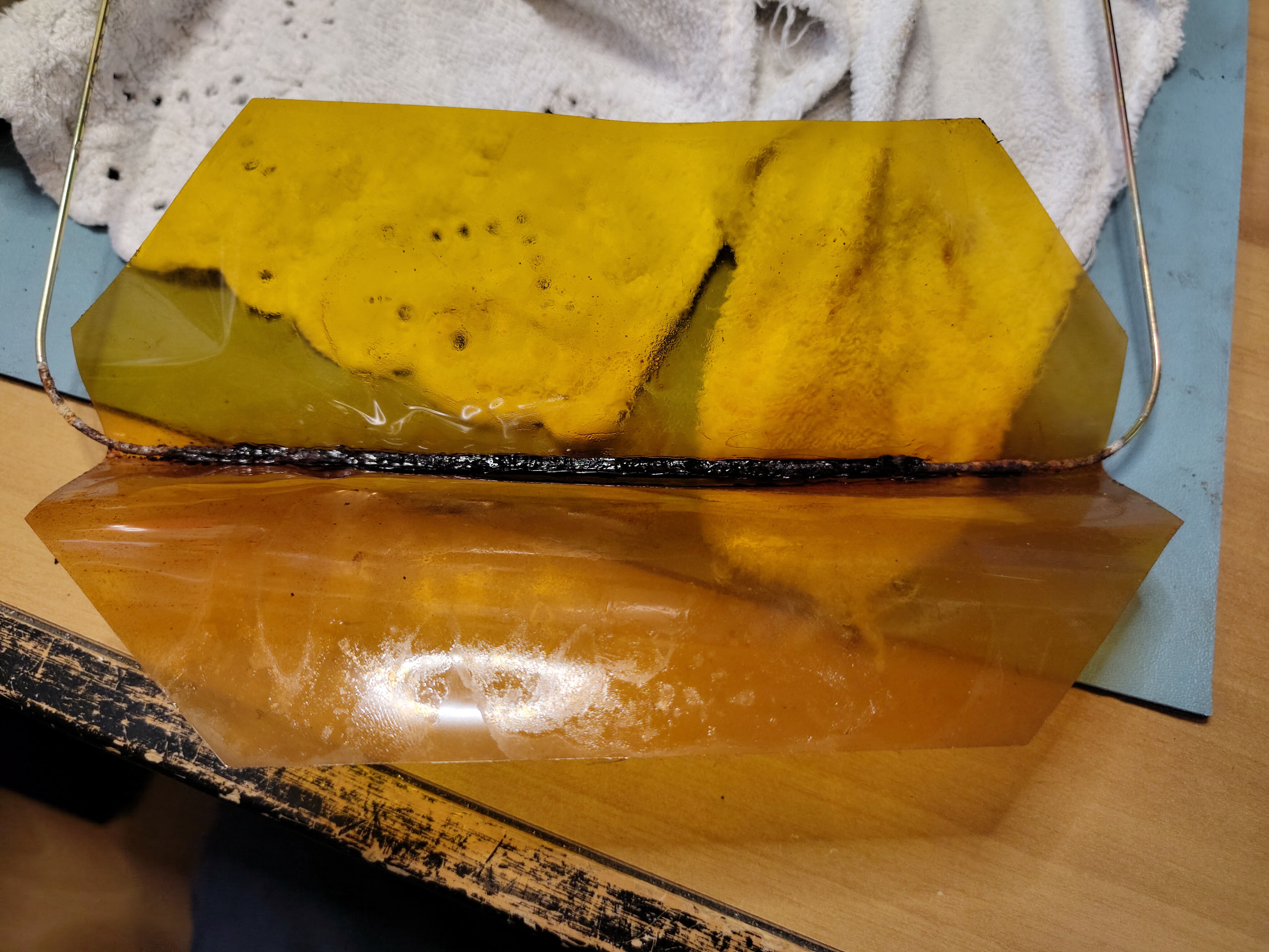
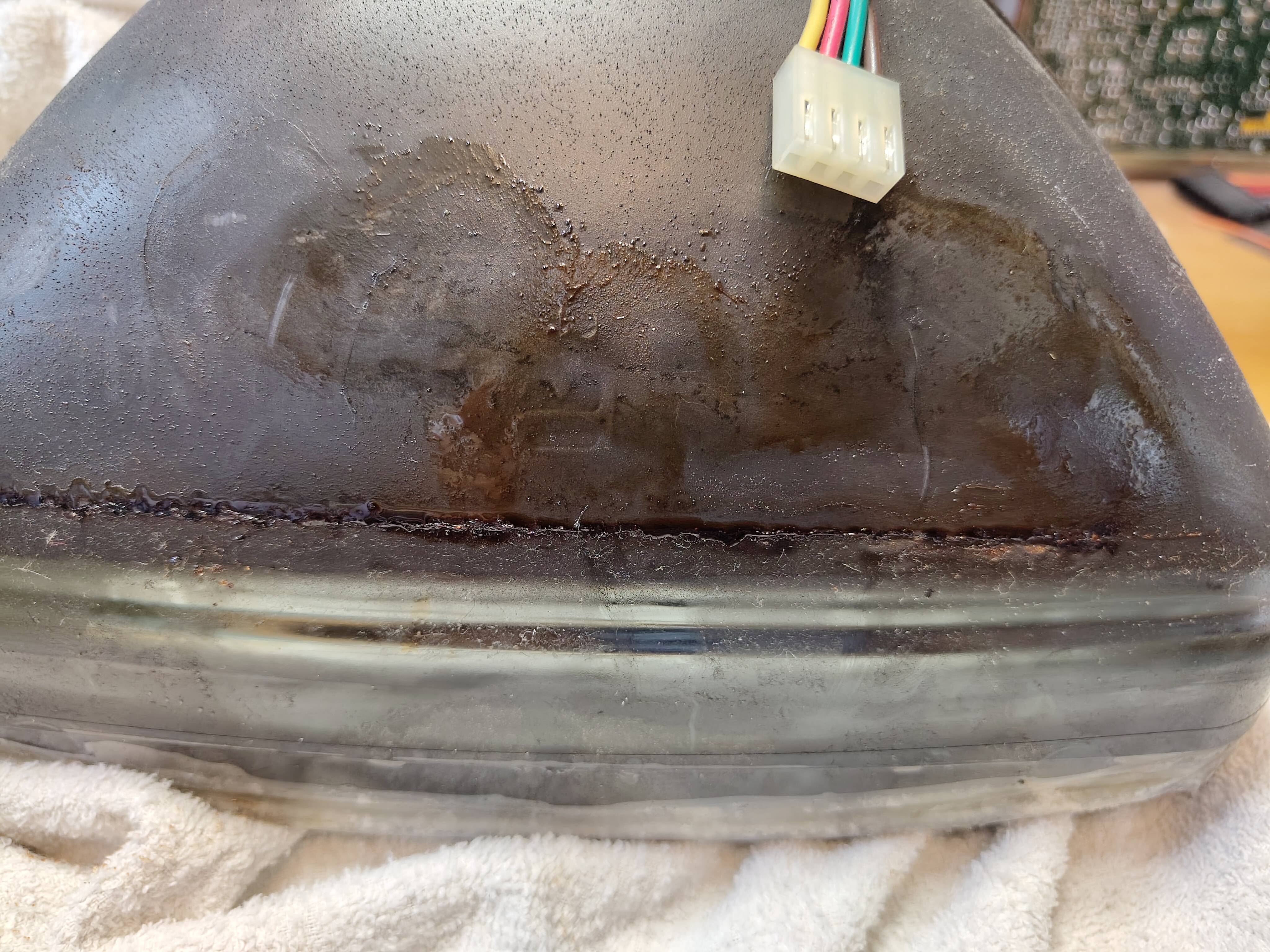
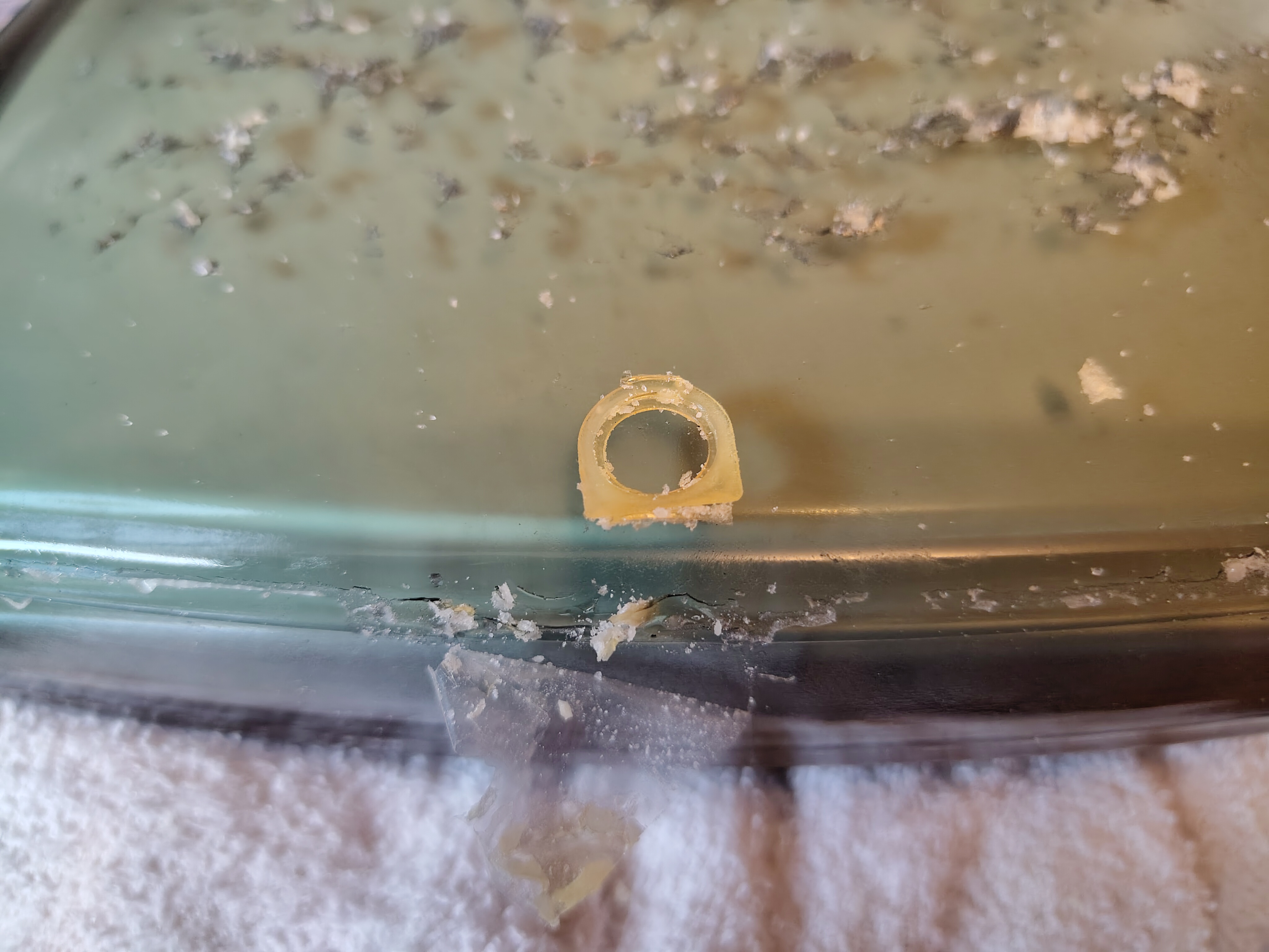
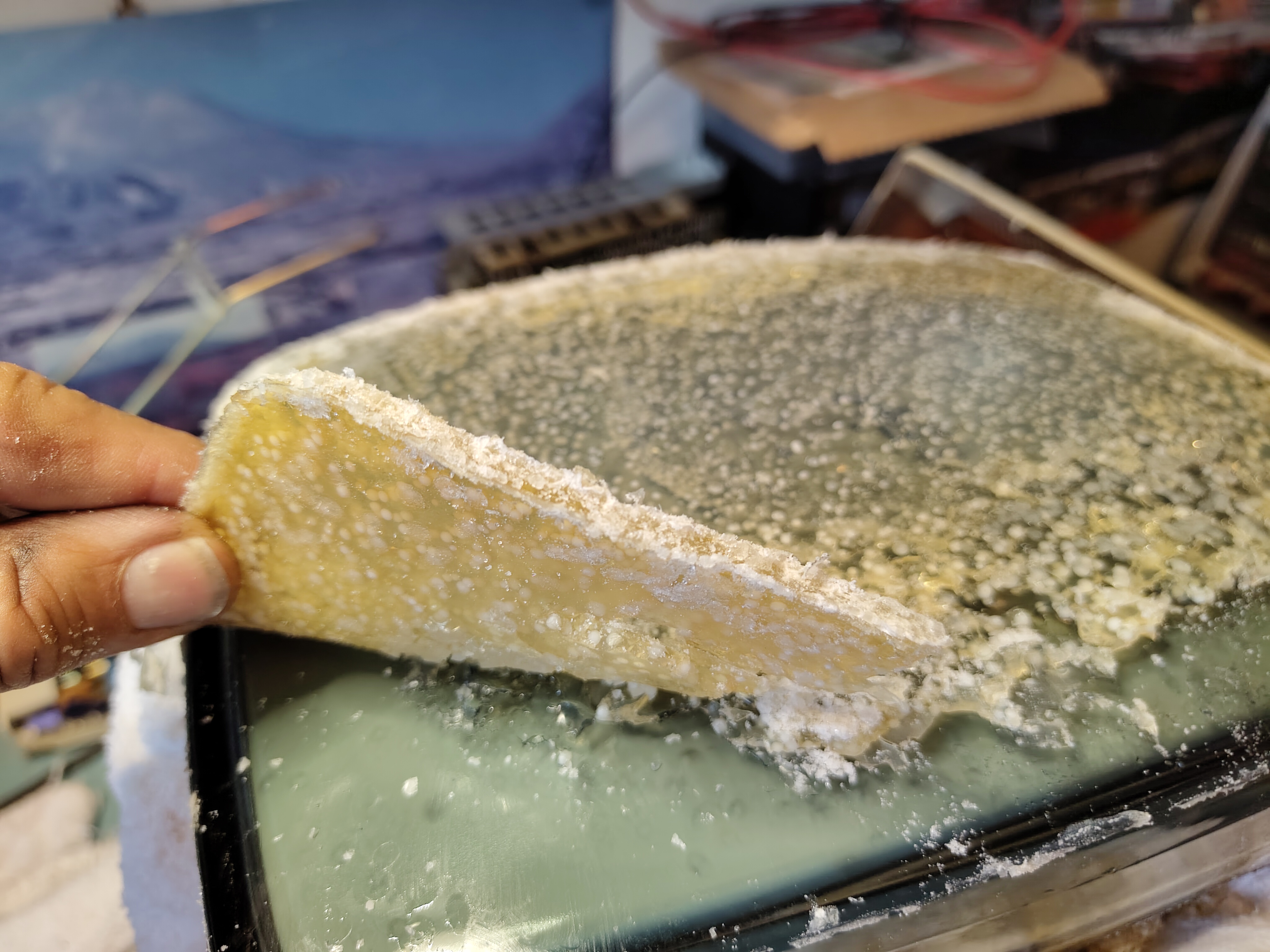
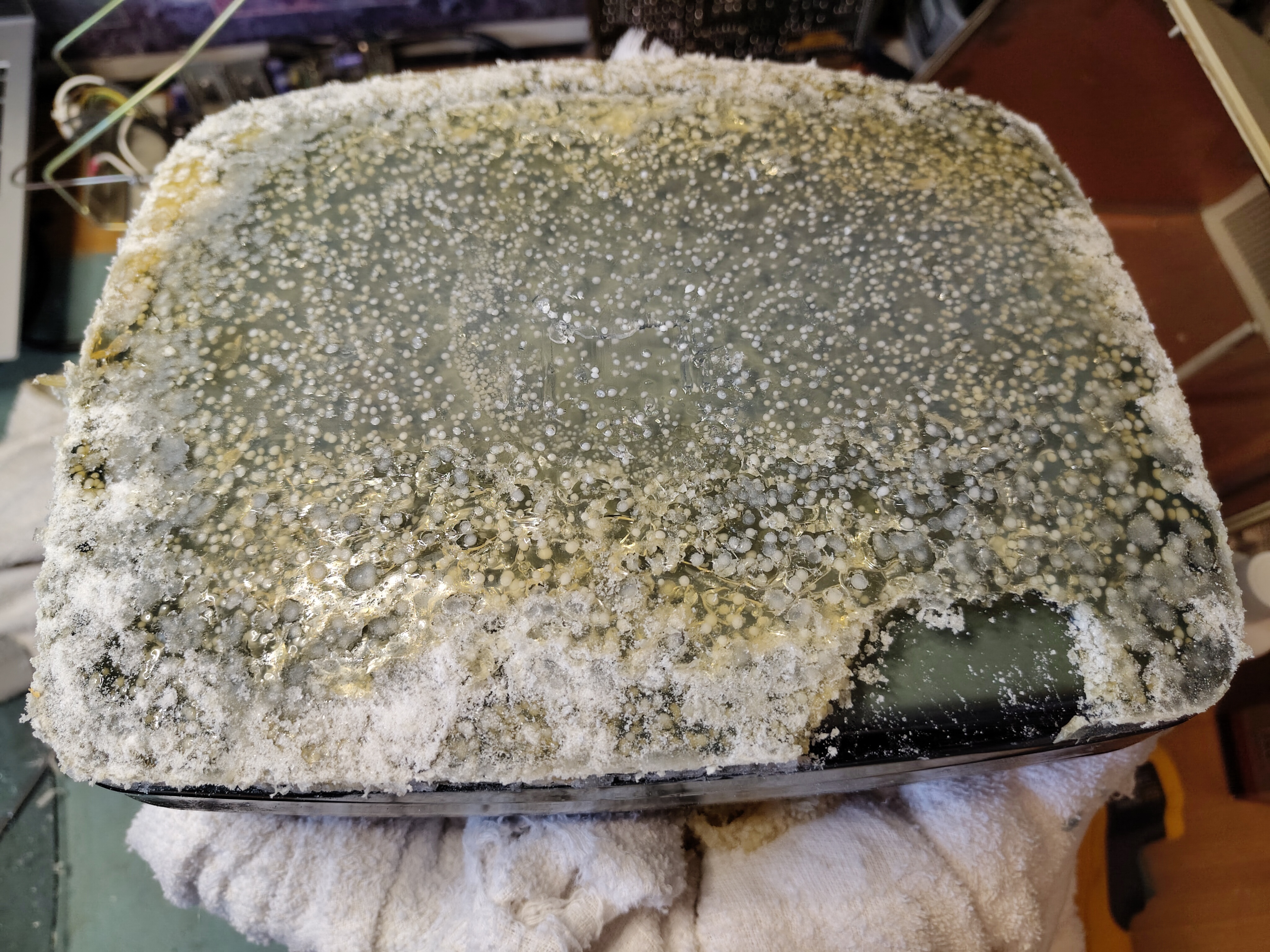
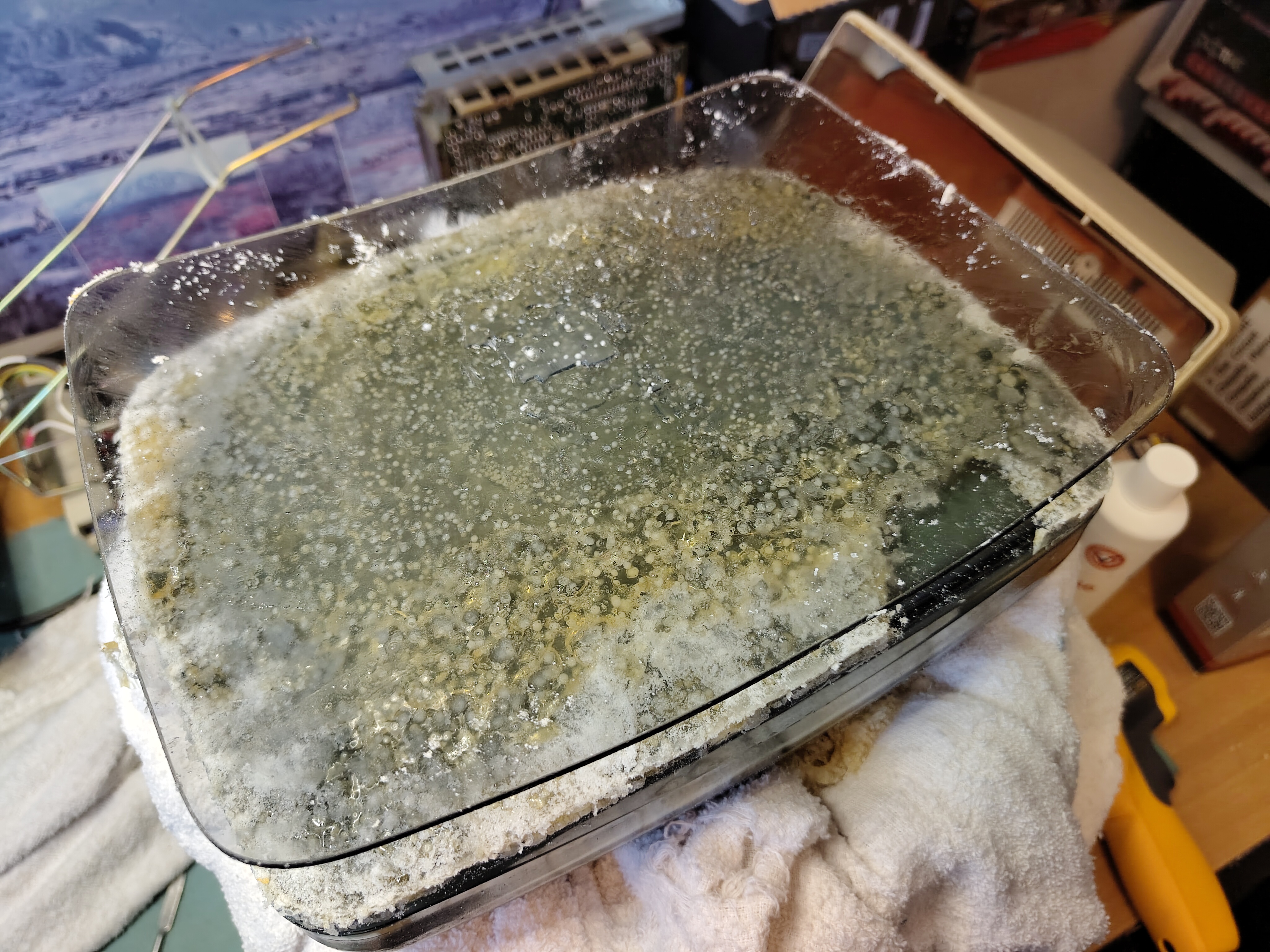
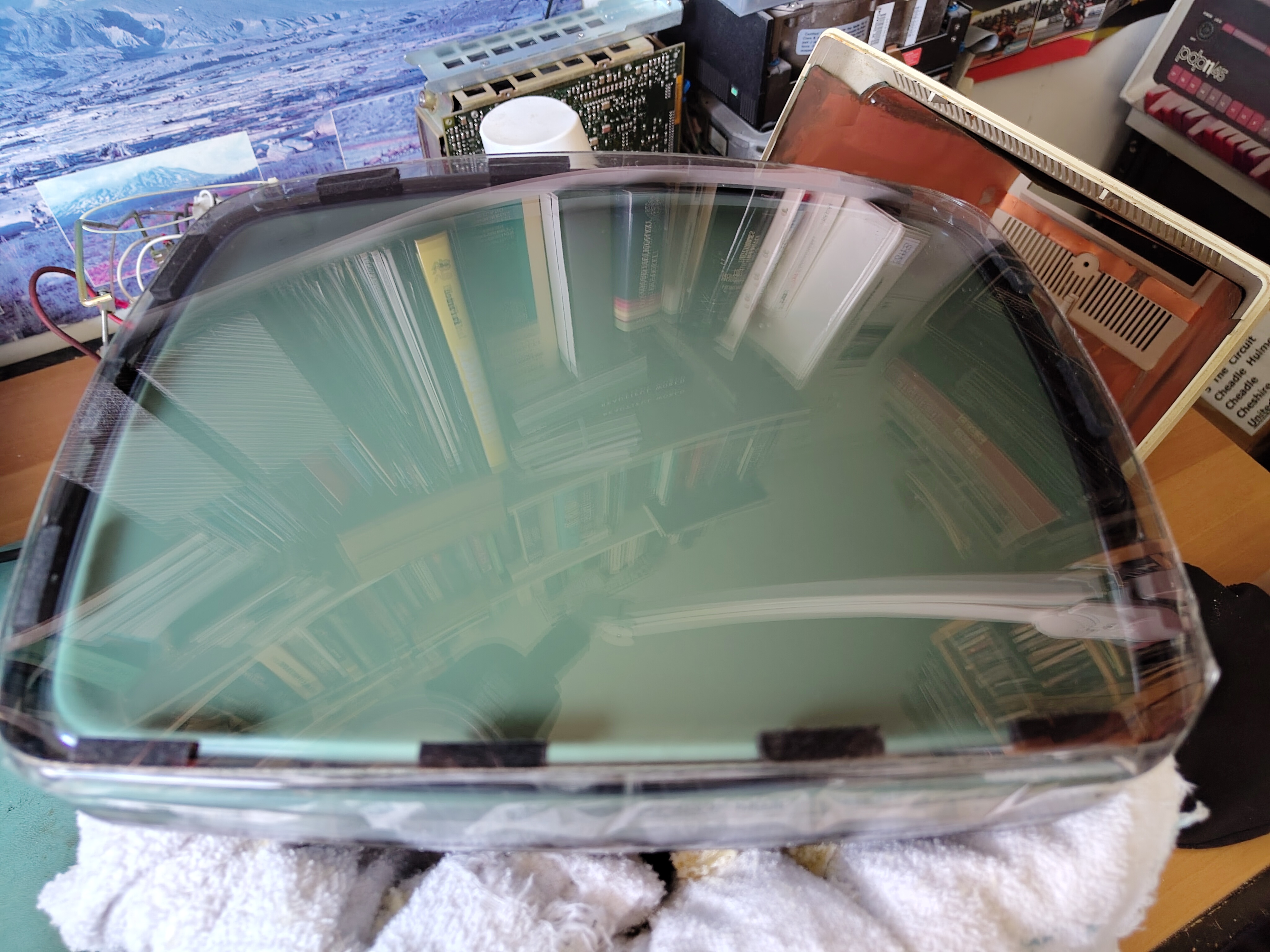
I used an ordinary hair dryer over the front glass to soften the glue underneath and gently worked away at removing the front glass. I found that the hair dryer got the front glass to about 65-70 Celsius and that was enough. I measured the gap between the front glass and the tube at 0.57mm with a calliper.
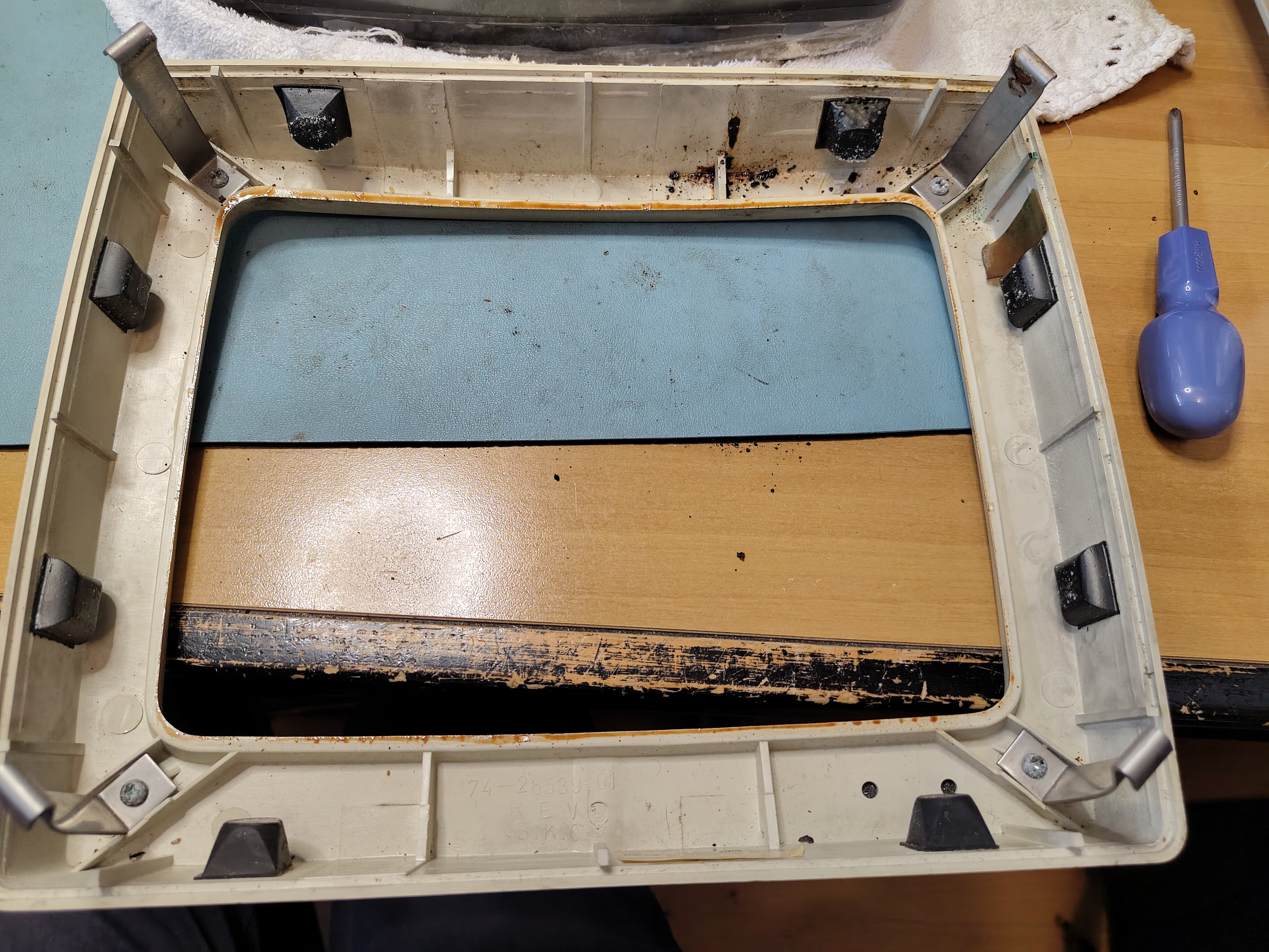
Eventually the front glass came away and I was able to peel most of the glue off with my fingers.
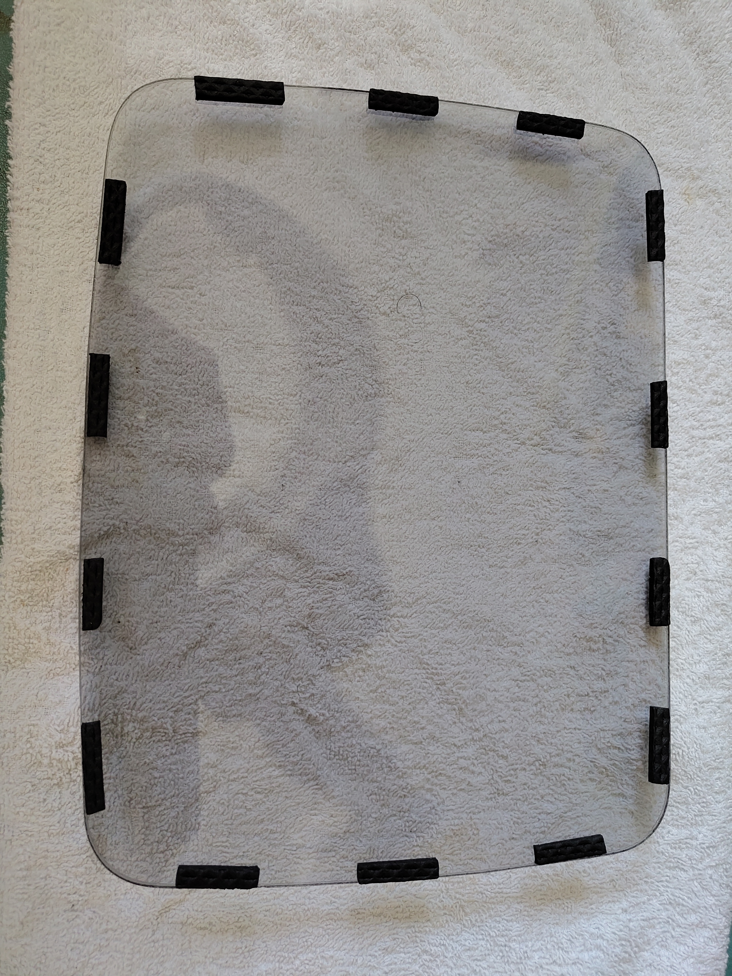
After careful cleaning I applied thin strips of rubber that had a self-adhesive on one side to the front glass. I placed it over the tube and held it in place with adhesive tape, which also serves to keep dust out.
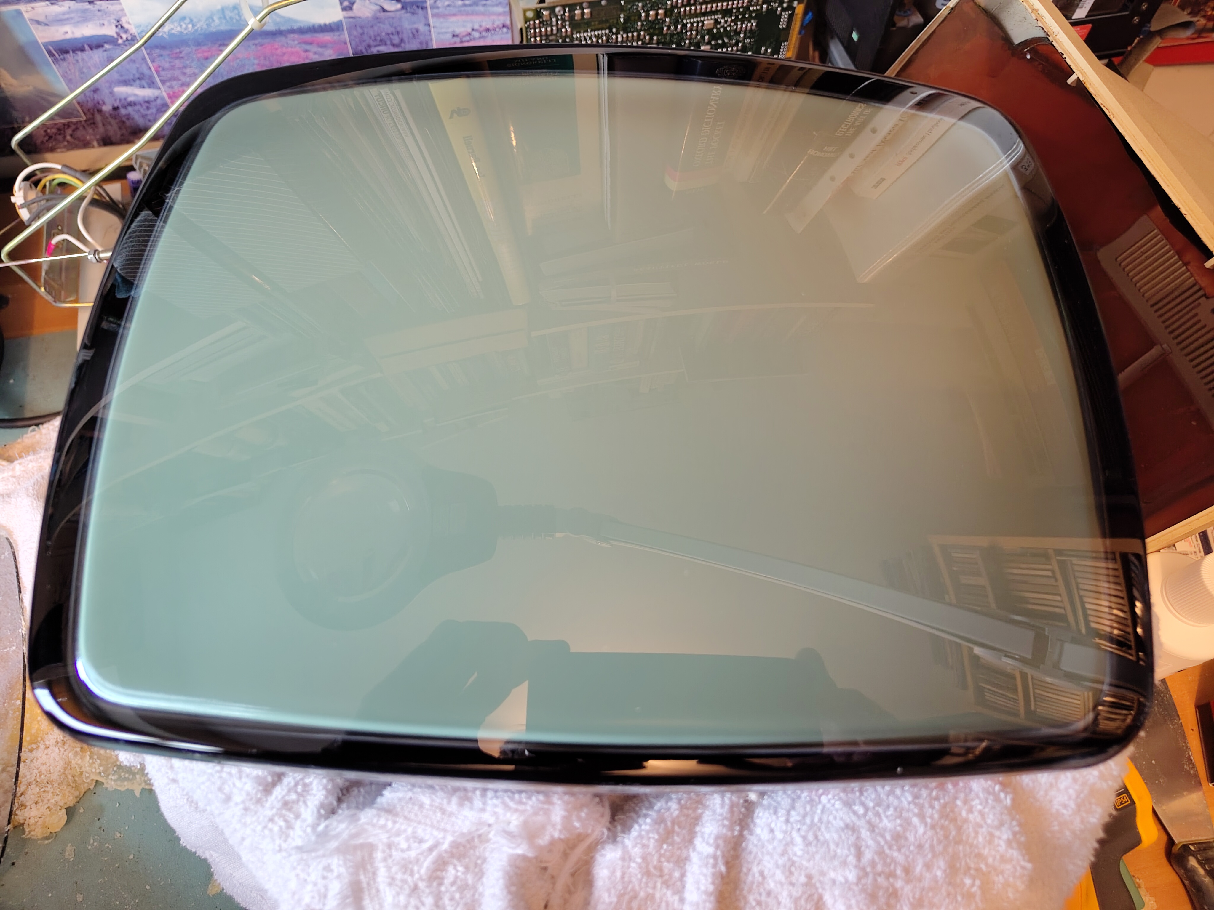
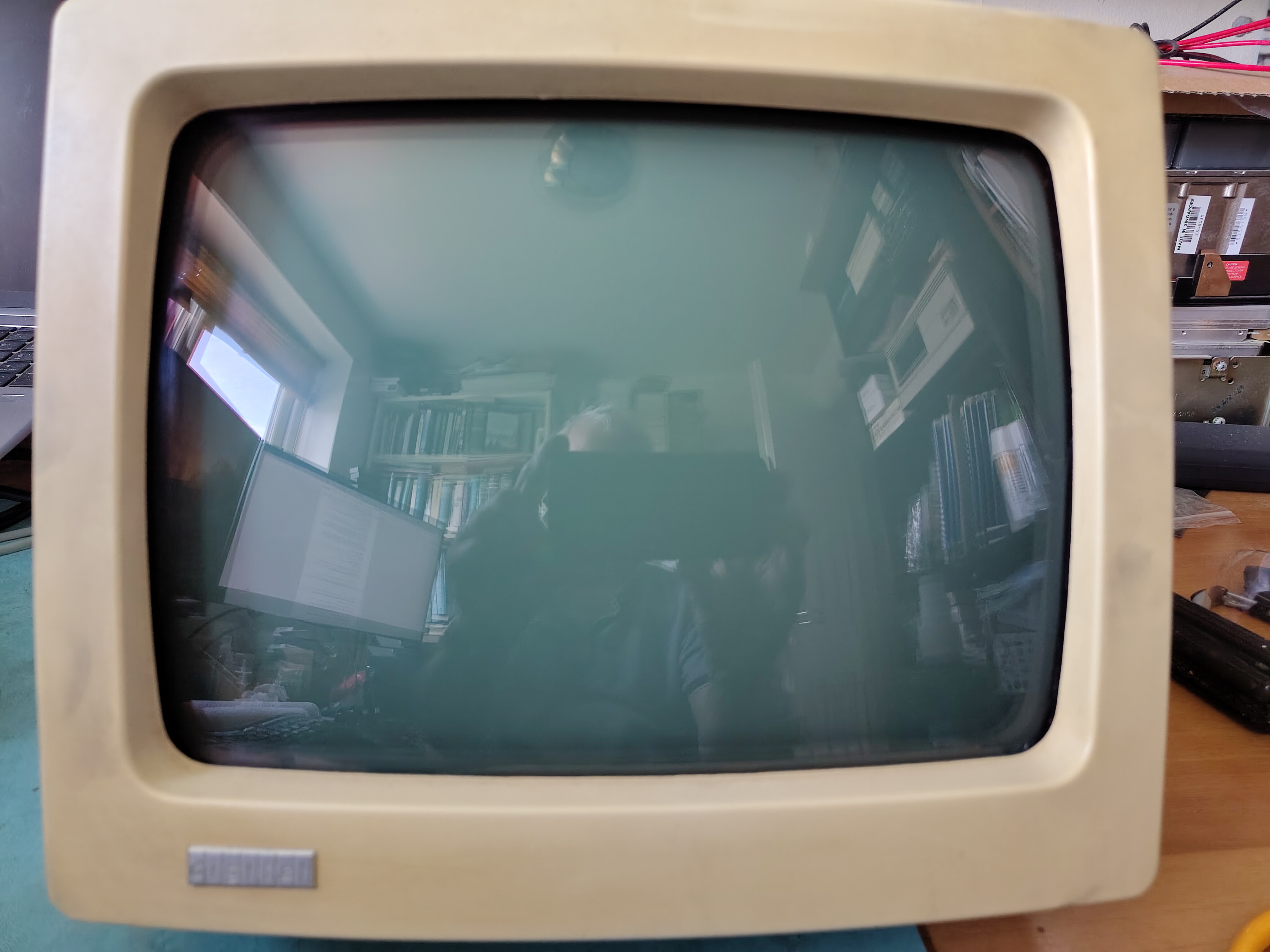
After reassembly the monitor looks good again.
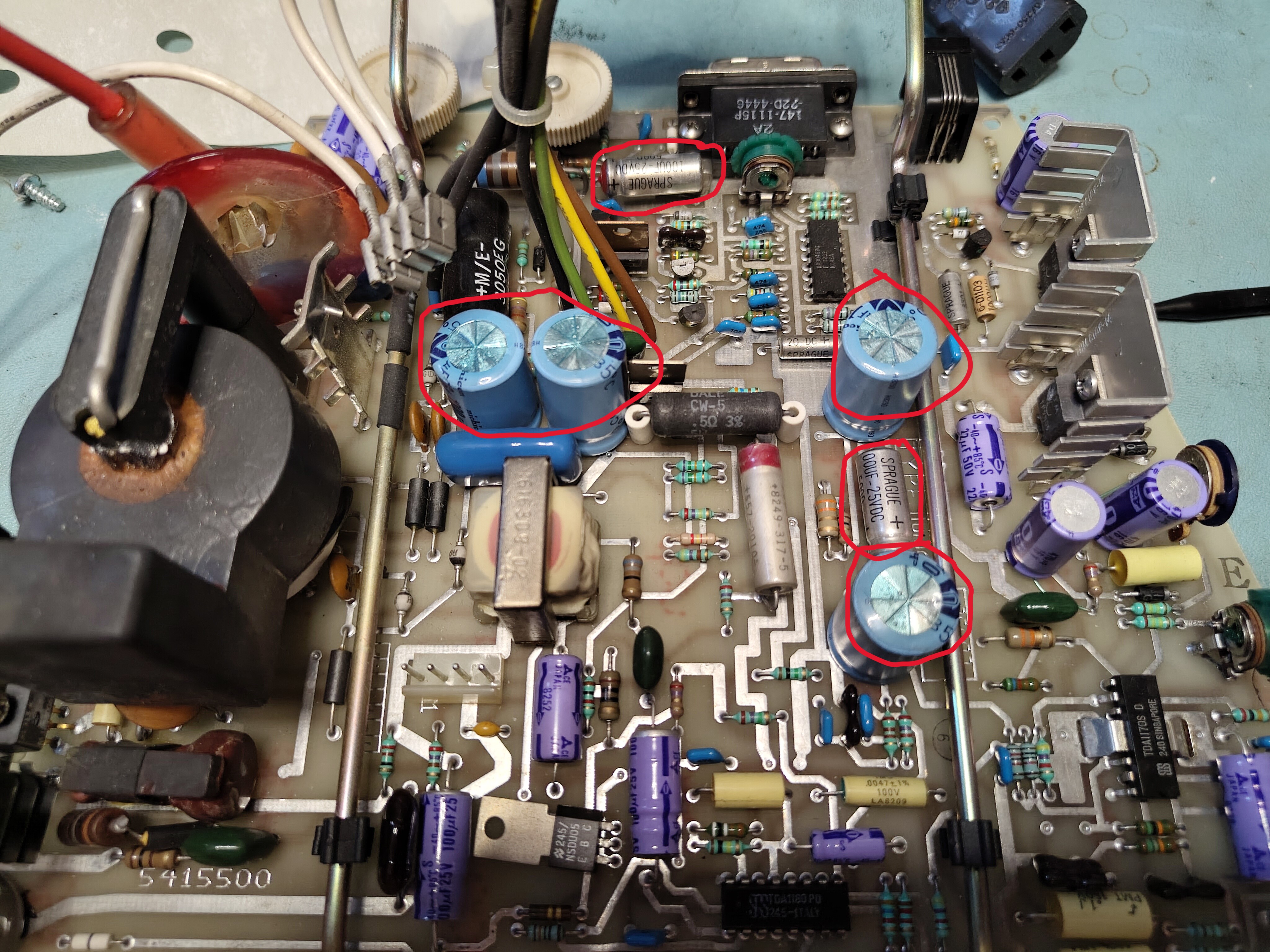
However I noted a slight shimmer in the display and struggled to get a bright display without the background being too bright. It looked like some of the electrolytic capacitors on the monitor board needed to be replaced. After examining them I found some had suspicious bulging or a high ESR, so I replaced C24, C30, C41 C303, C404 and C39 (as per the print set). They are the ones marked in the picture below.
After replacing the capacitors I put the VR201 back together again. The shimmer was still there, but it disappeared after a few minutes of operation. There is a faintly discernible vertical jitter, but very minor. Occasionally the monitor goes blank and a power cycle is needed. I don’t plan to look further at this for now.
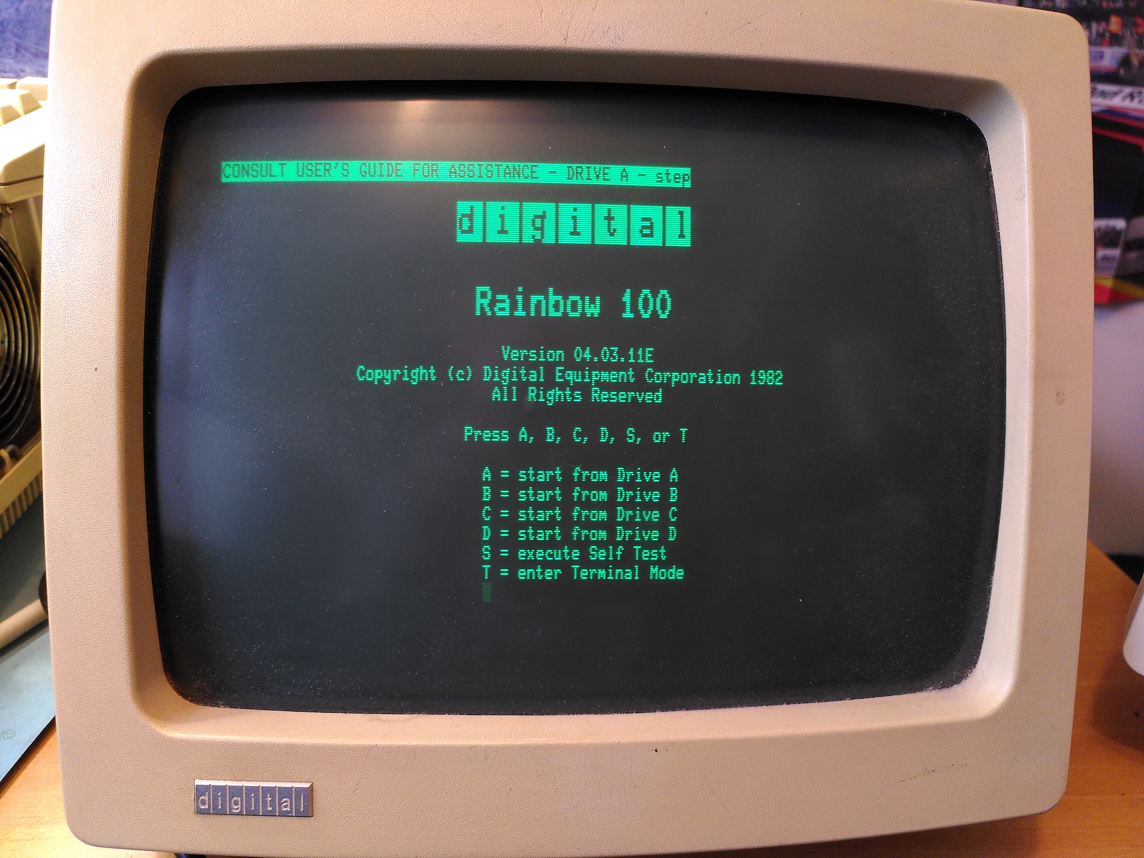
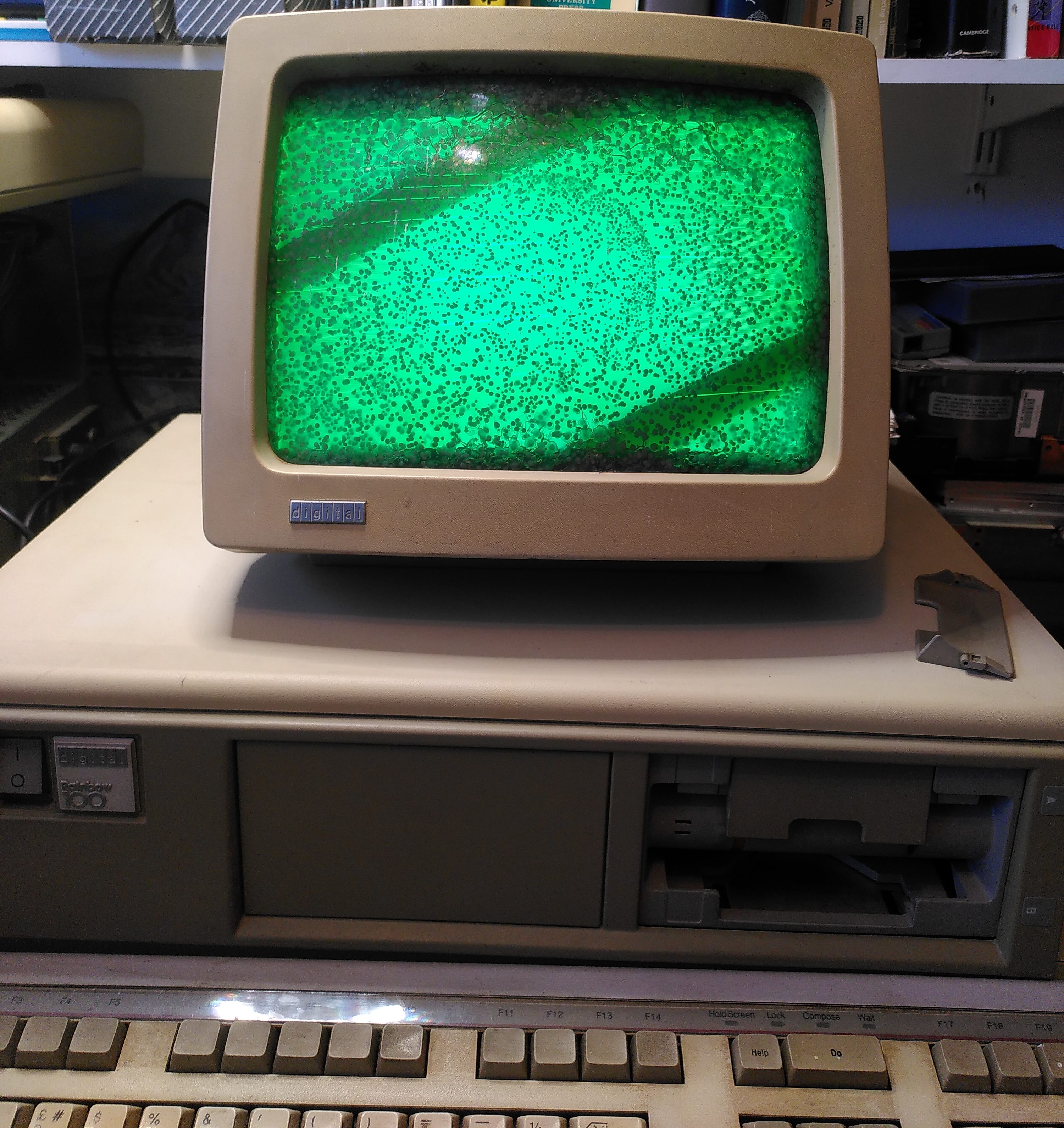
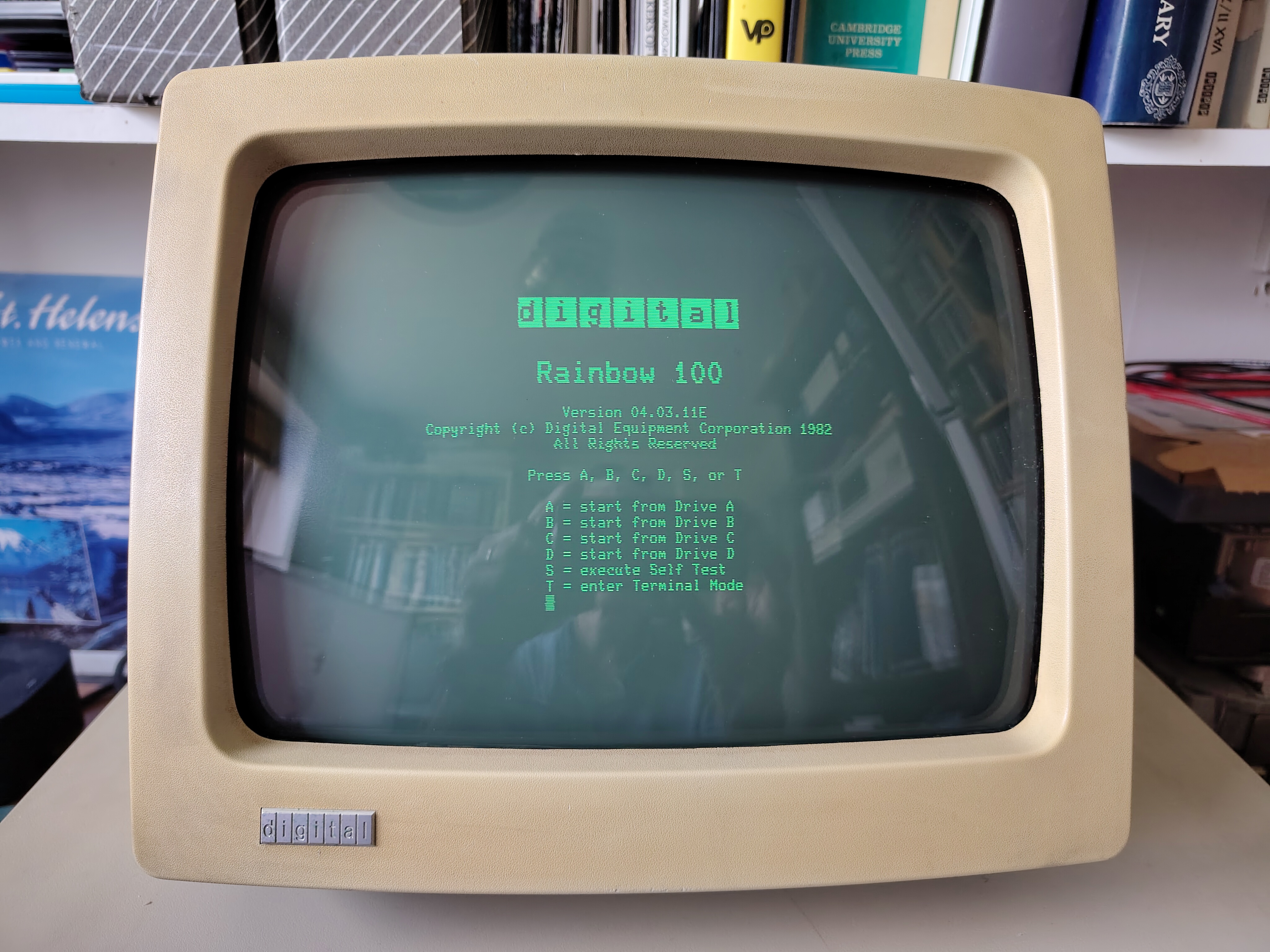
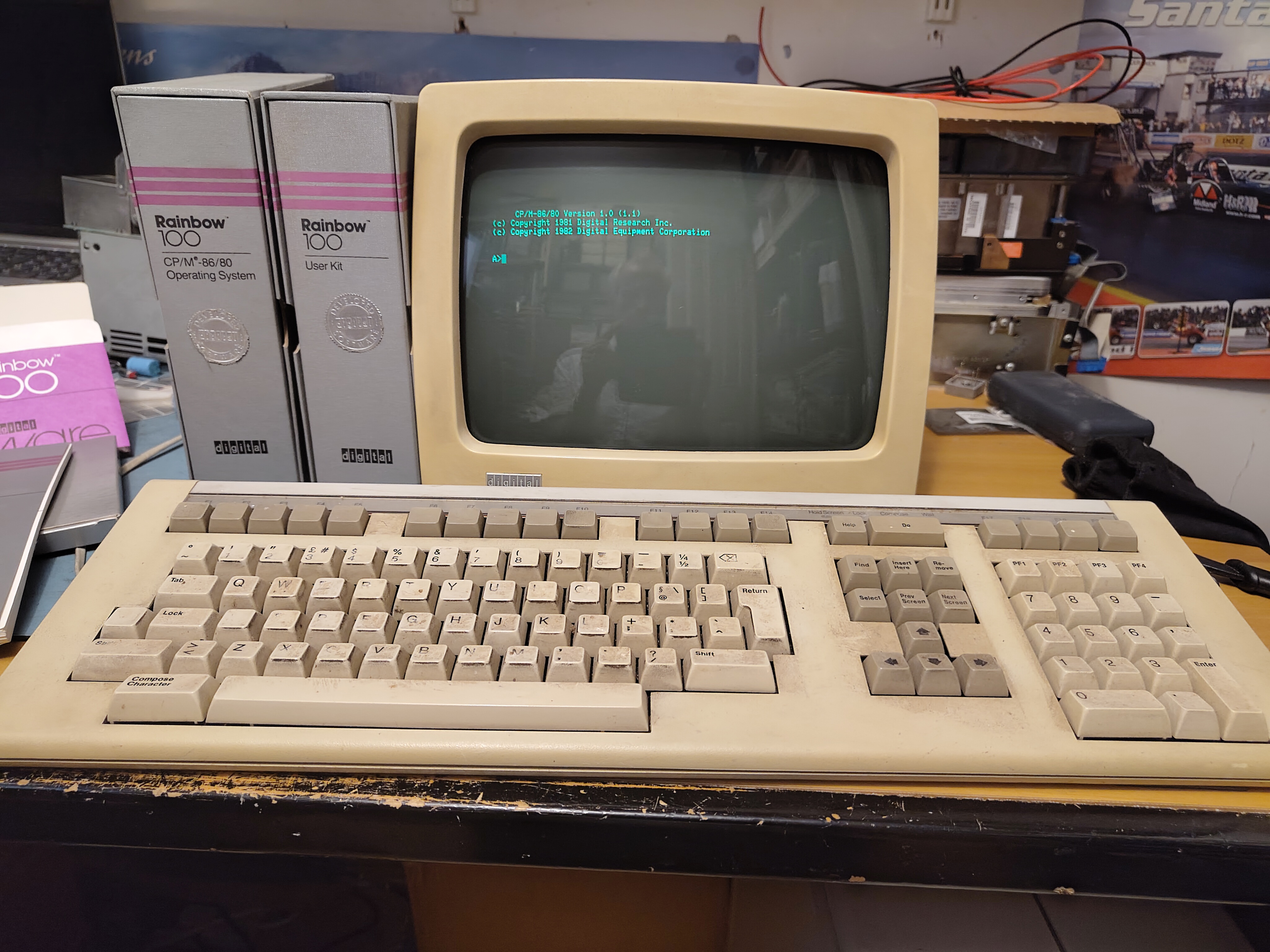
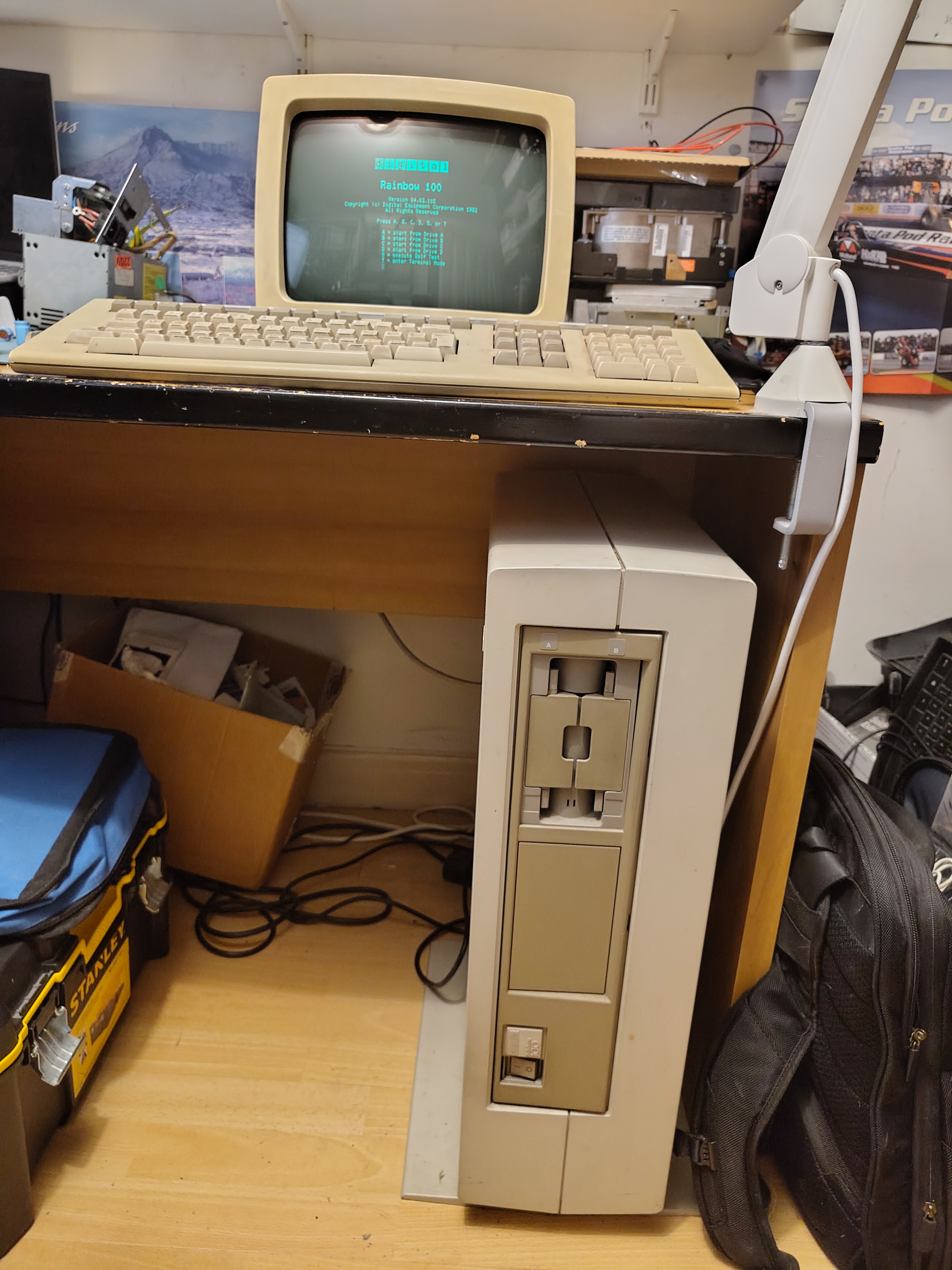
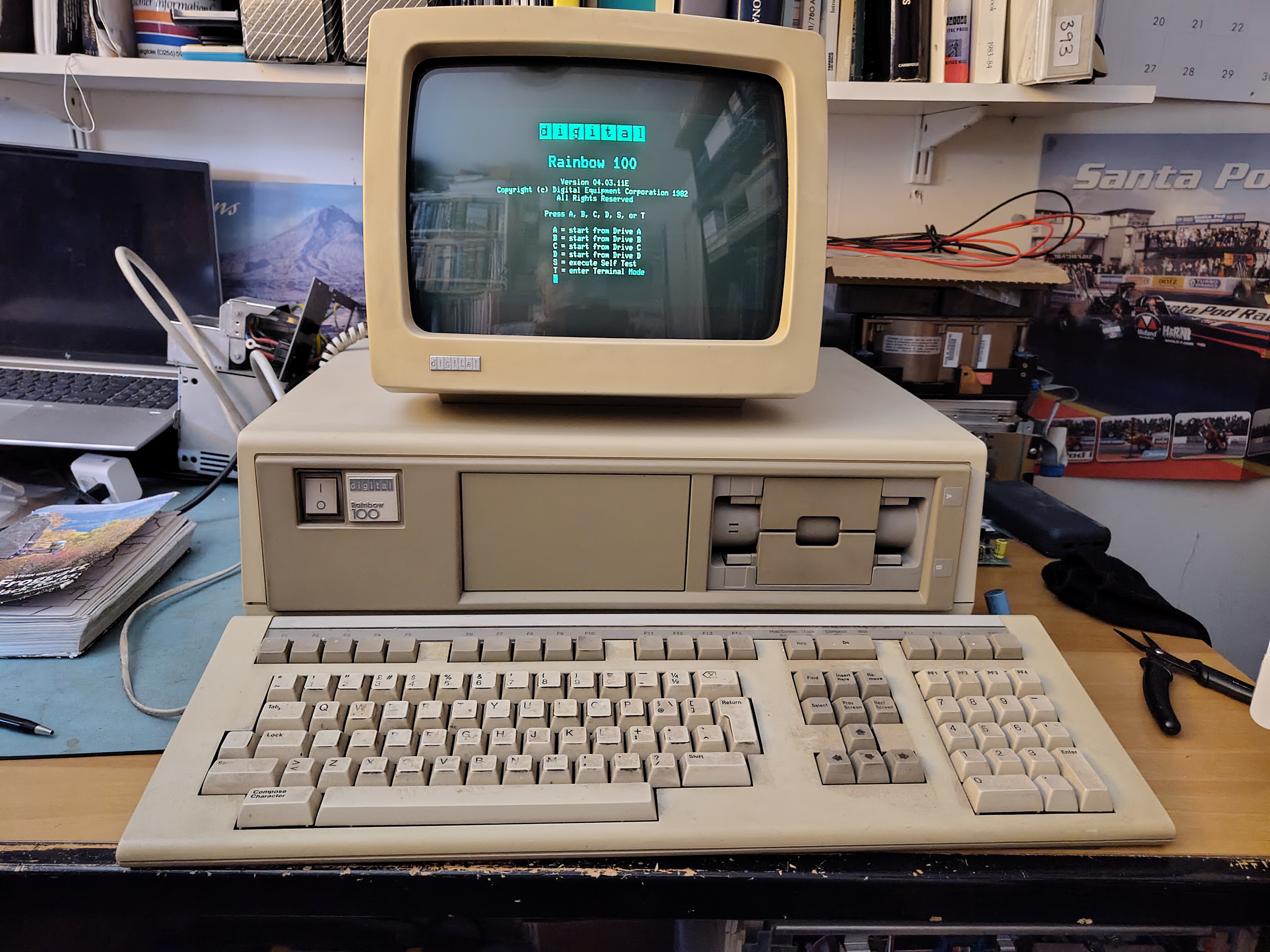
This is the Rainbow 100A working once more:

Top-notch work, Rob! You’ve officially introduced Gen Z to a whole new tech jungle we’re spotting gadgets here like it’s a hardware safari, and most of us are blinking at the screens like, ‘Wait… this exists?!’